
Precision Worm Gear Manufacturing on Universal Milling Machines
author: Cash
2026-07-11
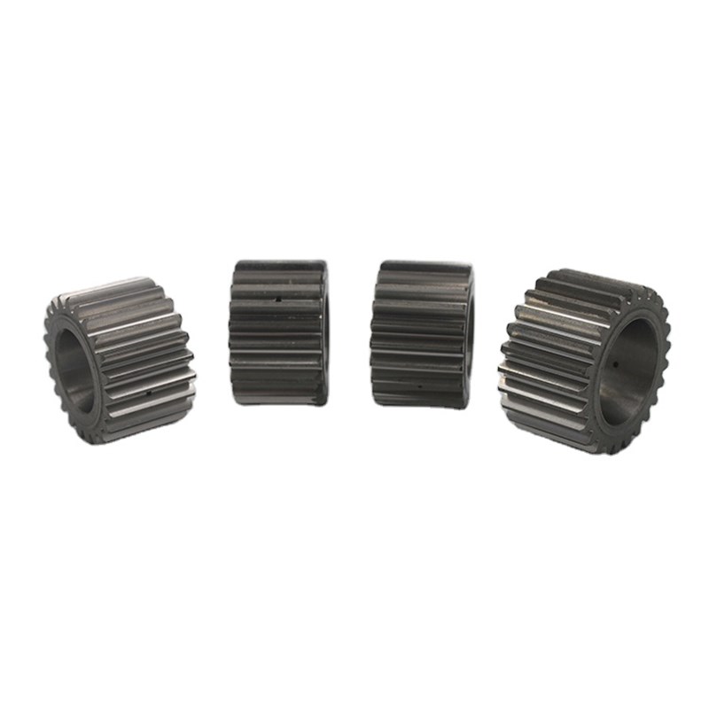
Precision Worm Gear Manufacturing on Universal Milling Machines: The Fly Cutter Generative Method | Gearseiko
Introduction
High-precision worm gear manufacturing often faces a typical industry dilemma: standard dedicated hobs deliver excellent precision yet come with high customization costs and long lead times, making them uneconomical for prototyping, equipment maintenance and small-batch production. As a professional precision gear manufacturer focusing on balanced quality and cost efficiency, Gearseiko adopts the mature fly cutter generative machining method on universal milling machines to solve this pain point.
This flexible and practical processing technology breaks the equipment and tooling limitations of traditional worm gear hobbing. It enables standardized, reliable worm gear production on common universal milling equipment, perfectly matching the processing demands of low-volume customization, engineering trial production and mechanical maintenance scenarios. This article systematically elaborates on the working principles, core advantages, technical limitations, standard setup parameters and complete machining procedures of the fly cutter generative method, providing actionable technical references for global engineers and procurement specialists.
1. Working Principle of Fly Cutter Generative Machining
The fly cutter generative method is derived from the inherent kinematic law of worm and worm wheel meshing transmission. In a standard gear pair meshing state, the axial section of the worm features a rack-like structure, which engages and drives the worm wheel to rotate like a spur gear. For a single-start worm, one full worm rotation corresponds to one axial pitch advance and drives the worm wheel to rotate by one tooth; for multi-start worms, the advance pitch and matching tooth rotation increase synchronously.
Traditional gear hobs are essentially toothed structural worms that realize continuous generative forming of gear teeth through high-speed rotation and meshing transmission. The fly cutter method simplifies this principle to the extreme: it adopts a single-tooth cutting tool (equivalent to a single independent tooth of a standard hob) fixed on a professional cutter arbor.
Through precise matching of replaceable change gears, the milling machine table’s longitudinal feed motion and the worm gear blank’s indexing rotation form a linkage generative system. When the workpiece blank rotates 1/z of a full circle (z stands for the total number of gear teeth), the milling table accurately advances by one standard tooth pitch, completing precise one-to-one profiling of a single tooth space. Repeating this cyclic motion realizes full-tooth high-quality generative machining of the worm gear.
2. Core Advantages of Fly Cutter Worm Gear Machining
Compared with conventional dedicated hob hobbing technology, the fly cutter generative method shows unique application value and economic advantages in small-batch and maintenance scenarios, with three core strengths:
2.1 Zero Custom Specialized Tooling, Ultra-Low Cost
Dedicated worm gear hobs are customized according to specific module, helix angle and tooth profile parameters, with high manufacturing costs and long delivery cycles. In contrast, fly cutters feature simple structures, easy on-site production and flexible adaptation to diverse worm gear specifications. They require no professional hob inventory investment, greatly reducing tooling procurement and storage costs for small-batch and sporadic production.
2.2 Decoupled Motion Design for Higher Machining Efficiency
A key technical advantage of this process is the independent operation of cutting speed and generative table feed. The spindle speed can be substantially increased without affecting workpiece indexing accuracy, breaking the speed limitation of traditional hobbing machines. For roughing processes, multi-tooth cutters and disc milling cutters can be matched to further improve material removal efficiency. In batch roughing scenarios, its comprehensive productivity even surpasses conventional professional gear hobbing equipment.
2.3 Ideal Solution for Prototyping and Maintenance Production
Equipment maintenance, mechanical repair and product prototype verification are mostly single-piece or small-batch orders. Customizing exclusive hobs for each non-standard or special-spec worm gear will generate huge time and cost waste. The fly cutter method eliminates long lead-time tool customization, enabling fast response and low-cost production of small-batch worm gears, fully meeting the urgent delivery demands of after-sales maintenance and project trial production.
3. Technical Limitations & Applicable Scenarios
Although the fly cutter generative method has prominent economic and flexible advantages, it has inherent technical limitations due to the structural characteristics of universal milling machines, requiring reasonable scenario selection in actual production.
Different from professional hobbing machines with differential compensation systems, universal milling machines only rely on fixed longitudinal table feed for generative machining without differential motion adjustment. This leads to approximate forming of helical tooth profiles instead of standard mathematical spiral curves. The profile error remains tiny and negligible for worm gears with small helix angles and narrow tooth widths.
However, for workpieces with large helix angles or wide face widths, the cumulative approximation error will increase significantly, failing to meet high-precision transmission standards. Therefore, this process is mainly applicable to medium-precision general-purpose transmission worm gears, mechanical maintenance parts and non-critical drive systems. For high-precision and heavy-load core transmission worm gears, Gearseiko still adopts standard hob hobbing technology to guarantee extreme precision stability.

4. Critical Setup & Precision Adjustment Parameters
Standardized setup and precise parameter calibration are the keys to improving the machining accuracy and consistency of fly cutter worm gears. Gearseiko summarizes mature and reliable standard adjustment specifications based on long-term production practice:
4.1 Generative Motion & Indexing Parameter Calibration
The core of generative motion simulation is rack-and-gear rolling kinematics, realized through accurate change gear matching. The equipment must ensure synchronous coordination: the worm wheel rotates one tooth at a time, and the milling table advances one complete circular pitch accurately. In actual operation, the indexing head’s lubrication state and real-time temperature must be strictly monitored. When the spindle speed exceeds 80 r/min, equipment wear will accelerate, easily causing indexing deviation and precision attenuation, so speed parameters need to be reasonably limited according to processing conditions.
The whole gear circumference adopts single-step precise indexing for tooth division to ensure uniform tooth spacing and consistent circumferential distribution of all tooth grooves, avoiding meshing jitter caused by uneven tooth pitch.
4.2 Cutter Angle & Tool Alignment Standards
The milling head needs to be precisely swiveled to match the worm wheel’s helix angle, ensuring the fly cutter arbor is completely perpendicular to the tooth trace at the workpiece throat, which is the premise of standard tooth profile forming. During tool setting, the cutter tip must be aligned to the nearest position of the worm wheel throat center.
Gearseiko adopts a practical double-point alignment verification method: manually rotate the cutter arbor to check whether the cutter tip makes uniform and consistent contact with the A and B edge points of the blank outer circle. Only after eliminating unilateral deviation can formal machining be carried out to effectively avoid tooth profile deflection and asymmetric tooth grooves.
5. Gearseiko’s Standard Fly Cutter Machining Procedure
We implement standardized full-process operating specifications for fly cutter worm gear milling to ensure repeatable stable quality for every batch of workpieces:
Step 1: Workpiece Precision Setup Fix the indexing head at the designated position of the milling table, adjust the spindle to a vertical state, clamp the worm gear blank on the mandrel via a self-centering chuck, and strictly detect and correct workpiece concentricity to eliminate circular runout errors.
Step 2: Professional Tool Installation Fasten the fly cutter tool bit on the special arbor, integrally mount the arbor on the universal milling machine spindle, and lock it firmly with a drawbar to prevent tool vibration and displacement during high-speed cutting.
Step 3: Helix Angle Angular Adjustment Swivel the milling head according to the workpiece’s helix angle and helix direction, so that the arbor axis matches the tooth trace angle of the worm wheel, adapting to the helical forming law of gear teeth.
Step 4: Centerline Accurate Alignment Fine-tune the cutter position to ensure the cutting edge centerline falls exactly on the worm wheel’s central plane, avoiding tooth profile offset and unilateral cutting deficiency.
Step 5: Parameter Double Verification Recheck all change gear matching calculations, generative motion parameters and indexing data to eliminate manual calculation errors.
Step 6: Change Gear Installation & Direction Confirmation Install the matched change gears, verify the rotation direction of the blank and table feed, and add intermediate gears for adjustment if the direction is reversed to ensure consistent motion logic.
Step 7: Trial Cutting & Angle Correction Perform ultra-light shallow trial cutting to form obvious witness marks, detect the actual helix direction and helix angle with a universal bevel protractor, and fine-tune the milling head angle in case of deviation to meet design standards.
Step 8: Formal Roughing & Finishing Machining Machine each tooth groove sequentially, retract the table transversely after processing each tooth to avoid tool scratching the tooth surface during indexing. Adopt separate roughing and finishing passes to remove machining allowance and ensure excellent surface roughness and dimensional accuracy.
Step 9: Post-Machining Precision Inspection Use a professional gear tooth vernier caliper to measure chordal tooth thickness after processing the first tooth. Fine-adjust the center distance between the fly cutter arbor and the worm wheel center according to the measured data, then complete the processing of remaining teeth to ensure full-batch consistency.
6. Why Partner with Gearseiko for Worm Gear Manufacturing?
With decades of accumulated precision gear manufacturing experience, Gearseiko flexibly matches diverse processing technologies for different customer demands. For high-precision core transmission scenarios, we adopt professional hob hobbing technology to achieve ultra-high precision tooth profiles; for maintenance, prototyping and medium-precision general-purpose scenarios, we apply optimized fly cutter generative milling technology to balance quality, cost and delivery efficiency perfectly.
We provide one-stop full-service support covering tooling scheme customization, process parameter optimization, full-process precision inspection and after-sales technical guidance. Relying on standardized operating procedures and rich on-site debugging experience, we effectively avoid common defects such as tooth profile distortion, uneven tooth pitch and unqualified helix angle, delivering stable and reliable custom worm gear products for global industrial equipment, automation machinery and mechanical maintenance industries.

Conclusion
The fly cutter generative machining method on universal milling machines is a highly flexible, cost-effective and mature worm gear processing technology. Despite minor precision limitations in high-helix and wide-tooth workpieces, its irreplaceable advantages of no custom tooling demand, short production cycle and low manufacturing cost make it the optimal solution for single-piece prototyping, small-batch customization and equipment maintenance worm gear production.
Through standardized setup calibration and optimized process parameters, Gearseiko maximizes the machining stability and finished product quality of fly cutter worm gears, providing customers with diversified, high-cost-performance precision gear manufacturing solutions.
FAQ | Fly Cutter Worm Gear Milling Technology
Q1: What is the fly cutter generative method for worm gear manufacturing?
A1: It is a flexible machining technology applied on universal milling machines. It uses a single-tooth fly cutter and matched change gears to link workpiece indexing rotation and table longitudinal feed, simulating rack-gear meshing motion to complete accurate generative forming of worm gear teeth.
Q2: What are the biggest advantages of fly cutter milling over traditional hob hobbing?
A2: It requires no expensive custom worm hobs, features ultra-low tooling cost and short lead time. It supports fast small-batch and prototype production, with higher roughing efficiency, perfectly suitable for equipment maintenance and trial production scenarios.
Q3: What are the limitations of fly cutter worm gear machining?
A3: Without differential motion compensation, the machined helical tooth profile is an approximate curve. Error accumulates obviously for large helix angle and wide face width worm gears, so it is only suitable for medium-precision general-purpose transmission equipment.
Q4: What key parameters need calibration during fly cutter setup?
A4: Core calibration items include change gear generative motion parameters, indexing accuracy, milling head helix angle, cutter arbor verticality and workpiece centerline alignment, all of which determine the final tooth profile and meshing accuracy.
Q5: What scenarios are fly cutter milled worm gears suitable for?
A5: Ideal for mechanical equipment maintenance, product prototype verification, small-batch non-standard customization and non-critical general transmission systems, balancing cost and practicality perfectly.
Q6: Can Gearseiko ensure the quality consistency of fly cutter worm gears?
A6: Yes. We adopt unified standardized operating procedures, strict parameter verification and pre-production trial cutting calibration, plus post-process precision inspection, to ensure stable and consistent quality of all finished worm gears.
How Gearseiko Empowers High End Worm Wheel Machining with Craftsmanship
Fly Tool Generating for Worm Wheel Machining on Hobbing Machines A Complete Technical Guide
Related Article



