
Precision Calculation Guide for High Performance Drives
author: Cash
2026-06-04

Mastering the Geometry of Circular Arc Gears: Precision Calculation Guide for High-Performance Drives | Gearseiko
In premium heavy-duty power transmission fields, standard involute gears hit performance bottlenecks when projects demand ultra-high load bearing, low-noise smooth running and compact lightweight layout. Circular arc gears stand out as an optimized alternative solution. As a professional high-precision circular arc gear manufacturer, Gearseiko specializes in customized arc tooth gear system development and volume production; proficient geometric calculation serves as the core premise to fully release the structural advantages of circular arc tooth profile.Consult Gearseiko’s technical team to acquire free circular arc gear parameter calculation and tailored drive solution quotation.
Core Structural Feature of Circular Arc Gears
Different from conventional involute gears with line contact on transverse section, circular arc gears form instantaneous point contact on end face, resulting in zero transverse contact ratio (ε_α=0). This core mechanical feature determines circular arc gears cannot be designed as straight spur gears and must adopt helical tooth layout, which restricts all subsequent dimensional design and parameter matching of paired gear sets.
1. Fundamental Design Parameters & Axial Contact Ratio Constraint
Four core base parameters to confirm before design:
- Normal module (\(m_n\)): selected from international standard module series such as 2, 2.5, 3, 4mm
- Tooth count (\(z_1,z_2\)): conventional pinion & gear range 6~50 teeth
- Helix angle (\(β\)): common range 10°~30°, optimal design scope 15°~25°
- Face width (b): directly correlates with gear ultimate load capacity and contact stress
Owing to zero transverse contact ratio, total contact ratio equals axial contact ratio entirely. To realize uninterrupted stable meshing transmission, design must comply with: \(ε_β=\frac{b·\tanβ}{π·m_n}≥1.0\sim1.2\) This formula locks minimum required face width under fixed helix angle and normal module.
2. Unique Merit: Zero Undercutting Restriction
Unlike involute gears limited by minimum anti-undercut tooth number and profile shift correction, circular arc tooth contour is processed via circular arc forming cutter instead of involute generating machining. Root undercut and tooth profile interference never occur theoretically, enabling ultra-small tooth count design down to z=6 for ultra-compact high-reduction gearbox layout. Gearseiko realizes batch manufacturing of 6~8 teeth hardened ground circular arc pinions with mature craft to satisfy compact reducer customization demands.
3. Single & Double-Circular Arc Gear Classification & Production Difference
Single-Circular Arc Gear
Pinion adopts convex arc tooth while matching gear is concave arc profile; two exclusive forming cutters are required for separate machining. Higher tool procurement cost and spare part management cost restrict its modern large-scale popularization, gradually phased out in most new projects.
Double-Circular Arc Gear
Pinion and driven gear share identical basic arc tooth geometry, one set of hobbing cutter or rack cutter finishes machining for both gears. Remarkably reduces tooling expense, simplifies production flow and improves gear interchangeability. Gearseiko prioritizes double-circular arc structure for nearly all new custom gear design schemes.
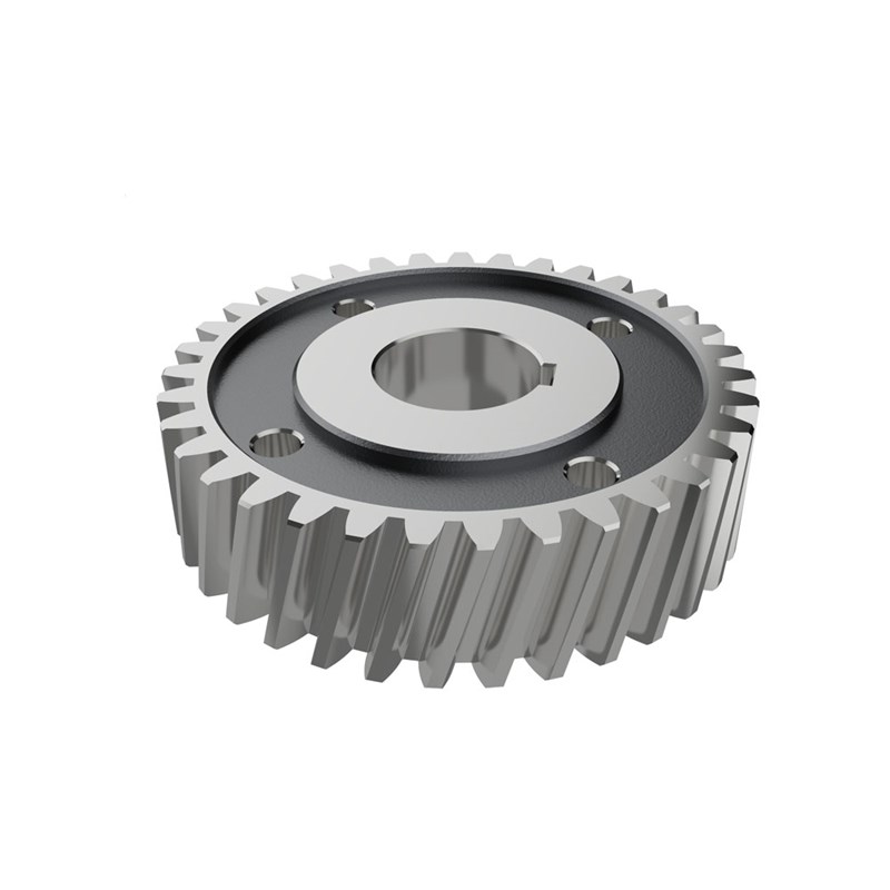
4. Standard Calculation Formulas for Double-Circular Arc Helical Gears
| Parameter | Symbol | Calculation Rule |
|---|---|---|
| Normal Module | mn | User defined standard value |
| Transverse Module | mt | mt=mn/cosβ |
| Pitch Diameter | d | d=z⋅mt |
| Addendum & Tip Diameter | ha,da | ha≈0.8mn, da=d+2ha |
| Dedendum & Root Diameter | hf,df | hf≈1.0mn, df=d−2hf |
| Center Distance | a | a=(d1+d2)/2 |
| Axial Contact Ratio | εβ | εβ=π⋅mnb⋅tanβ |
| Convex Arc Radius | ρa | 1.0~1.5mn, matched with nominal pressure angle |
| Concave Arc Radius | ρf | Slightly larger than ρa to reserve meshing clearance |
Note: Circular arc gears abandon conventional fixed pressure angle definition of involute gears; nominal pitch point pressure angle is commonly 20°~25°, while actual meshing contact angle changes dynamically along tooth height direction.
5. Practical Engineering Calculation Case (Gearseiko Standard Specification)
Design parameter: \(m_n=3\mathrm{mm},\ z_1=12,z_2=48,\ β=20°,b=40\mathrm{mm}\)
- Transverse module: \(m_t=3/\cos20°≈3.192\mathrm{mm}\)
- Pitch diameter: \(d_1=12×3.192=38.30\mathrm{mm},\ d_2=48×3.192=153.22\mathrm{mm}\)
- Center distance: \(a=(38.30+153.22)/2=95.76\mathrm{mm}\)
- Axial contact ratio: \(ε_β=\frac{40×\tan20°}{π×3}≈1.545>1.0\) (Meet design threshold)
- Outer & root diameter (\(h_a=2.4\mathrm{mm},h_f=3.0\mathrm{mm}\)): \(d_{a1}=43.10\mathrm{mm},\ d_{a2}=158.02\mathrm{mm},\ d_{f1}=32.30\mathrm{mm},\ d_{f2}=147.22\mathrm{mm}\) This finished double circular arc gear set features high load capacity and low vibration noise after precision processing, widely applied in heavy-load customized drive assemblies.
Gearseiko Core Manufacturing Advantages for Circular Arc Gears
- Professional arc profile precision grinding, finished tooth surface roughness Ra<0.4μm to reduce meshing abrasion and noise;
- Integrated CNC hobbing for double arc gears, single cutter realizes dual-piece production to control customer comprehensive cost;
- Diversified steel grades including 18CrNiMo7-6 and nitriding special steel, finished heat treatment hardness controlled at 58~62HRC;
- Machining accuracy up to ISO1328 Grade5~6, full CMM three-coordinate inspection for arc radius and tooth geometry;
- One-stop technical support: parameter calculation report + 3D design model delivery before formal production.
Our circular arc gears serve multiple industries: high-speed turbine transmission, heavy-duty extruder drive and compact robot joint actuator.
Custom Cooperation Guidance
Circular arc gear design needs professional geometric computing but brings prominent benefits: 30% higher load capacity vs standard involute gears, lower sliding friction loss and quieter running performance. Submit your equipment rated power, input speed and installation space limitation to Gearseiko’s engineering team, we complete full-set geometric calculation and optimize targeted circular arc gear solution.
Gearseiko – Precision in Every Arc.
FAQ | Circular Arc Gear Geometry & Production
Q1: Why circular arc gears cannot be manufactured as straight spur gears?
A1: End-face point contact leads to zero transverse contact ratio; only helical layout generates effective axial contact ratio for continuous meshing.
Q2: What’s the biggest design advantage compared with involute gear?
A2: No undercut limit, available for ultra-small tooth count z=6~8 to realize compact high reduction ratio gearbox.
Q3: Difference between single and double circular arc gears?
A3: Single arc needs two different cutters with high tool cost; double arc uses one cutter for both gears with lower cost and better interchangeability.
Q4: Calculation standard of qualified axial contact ratio?
A4: ε_β≥1.0~1.2 to guarantee uninterrupted stable gear meshing.
Q5: What precision & material can Gearseiko supply?
A5: ISO1328 Grade5~6, Ra<0.4μm; optional carburizing/nitriding steel hardened to 58-62HRC.
A Precision Solution for Helical and Herringbone Gears
Gearseiko Helps You Choose the Optimal Transmission Solution
Related Article



