
Key Considerations in Hobbing Large Prime Number Cylindrical Gears Precision Practices for Superior Gear Manufacturing
author: Cash
2026-06-21
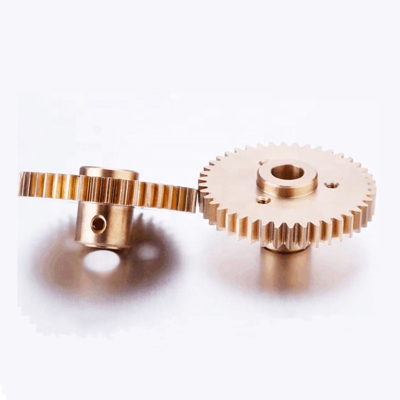
Key Considerations in Hobbing Large Prime‑Number Cylindrical Gears – Precision Practices for Superior Gear Manufacturing | Gearseiko
High-precision cylindrical gears with prime tooth counts over 100 are core transmission components for low-vibration, high-load industrial equipment, widely deployed in wind power generation, marine heavy-duty transmission, aerospace actuators and high-precision automated machinery. Different from conventional standard gear hobbing, the machining of large prime number cylindrical gears relies on three linked machine drive chains: indexing motion, axial feed motion and differential compensation motion. Any misoperation of the drive system, tool retraction procedure or feed parameter will lead to tooth disorder, tooth breakage and full workpiece scrappage. With years of mature mass production experience on large prime spur gears and helical gears, Gearseiko sorts out three non-negotiable key process precautions and standardized operation norms for on-site hobbing processing, helping manufacturers avoid common processing failures.
1. Complete Drive Chain Integrity: The Most Fundamental Non-negotiable Rule
Complete gear hobbing cutting requires four synchronous operating drive chains on traditional hobbing machines: main spindle drive chain, indexing generating chain, vertical axial feed chain and differential auxiliary compensation chain. For ordinary composite-tooth gears, partial disconnection of individual drive chains barely affects overall cutting accuracy. However, for large prime cylindrical gears adopting approximate indexing plus differential compensation technology, all three core motion chains (indexing, feed, differential) are tightly coupled and mutually restricted, and no arbitrary disconnection is allowed during the whole cutting cycle.
The risk of breaking drive chains is more prominent in large prime helical gear hobbing. Since the actual prime tooth count cannot be factorized, the machine adopts approximate virtual tooth count for indexing gear matching, and all motion errors are fully offset by the differential chain. Once any drive chain is disconnected accidentally, the original matched error compensation relationship will collapse instantly. Two typical processing defects will occur:
-
Minor fault: tooth disorder: The synchronous phase between hob and workpiece deviates, resulting in uneven tooth spacing and unqualified meshing performance
-
Severe fault: tooth breakage and workpiece scrappage: The relative position between hob cutting edge and workpiece tooth flank is completely disrupted, causing direct collision damage to gear teeth and hob cutter
2. Standardized Tool Retraction Process for Roughing and Finishing Cutting
Large prime gear hobbing adopts segmented cutting technology: rough cutting for most material removal and finishing cutting for final tooth profile and pitch precision optimization. Combined with the drive chain integrity requirement, rapid automatic tool retraction is prohibited after rough cutting.
2.1 Wrong Operation: Rapid Vertical Traverse Retraction
Activating the rapid vertical traverse motor to send the hob back to the initial cutting position directly will disconnect the synchronous linkage of indexing and differential chains. The phase matching between hob and workpiece will be lost completely, requiring time-consuming secondary tool setting and phase calibration before finishing cutting.
2.2 Standard Operation: Manual Crank Retraction
After finishing rough cutting, technicians manually shake the vertical slide to move the hob away from the workpiece steadily, and restore the equipment to automatic power feed mode before starting finishing cutting. This method keeps all drive chains connected without destroying the original synchronous phase, ensuring consistent cutting benchmark for rough and finish passes.
2.3 Permissible Condition for Mandatory Rapid Retraction
If rapid retraction is required to improve production efficiency under special production schedules, the retraction stroke must strictly follow one rule: the total retraction distance shall be an integer multiple of the gear axial pitch. Only in this way can the helix phase of helical gears remain matched, and no repeated tool setting is needed after rapid retraction.
3. Vertical Feed Rate Matching: Feed Adjustment Requires Full Differential Gear Recalculation
Many processing workshops only regard vertical feed rate as a parameter affecting cutting efficiency and workpiece surface roughness, ignoring its core linkage with differential compensation systems for large prime gears. In fact, the differential change gear ratio is calculated based on fixed vertical feed parameters.
For large prime gear hobbing solutions, differential motion is designed to compensate indexing deviation caused by approximate virtual tooth count. The compensation stroke, speed and direction of differential auxiliary motion are all bound to the vertical feed rate. Arbitrary modification of feed speed without parameter recalculation will cause mismatch between compensation motion and actual indexing error, leading to accumulated pitch error and distorted involute tooth profile.
Core Production Rule from Gearseiko Workshop: Once the vertical feed rate is changed, all differential change gear combinations must be recalculated, replaced and inspected. Different feed parameters correspond to exclusive differential gear sets, which cannot be used interchangeably in mass batch production.
4. Gearseiko’s Standardized Precision Manufacturing Management System
All the above operational details determine the final dimensional accuracy and transmission stability of large prime cylindrical gears. Gearseiko takes "precision comes from standardized process discipline" as our core production philosophy, and incorporates all critical hobbing precautions into mandatory SOP specifications for all front-line processing technicians.
-
Full-process chain linkage inspection before startup: Check the synchronization of indexing, feed and differential chains before every batch of production
-
Unified rough and finish cutting retraction standards: Ban unauthorized rapid retraction to avoid phase deviation risks
-
One-to-one gear ratio matching for each feed parameter: Build exclusive differential gear databases corresponding to different feed rates and machine models
-
Post-processing full-item precision detection: Test tooth pitch error, helix error and tooth profile error to verify compensation effect
We never rely on operator experience alone to process high-precision large prime gears. Rigid process constraints and unified operating standards eliminate human operation errors fundamentally, ensuring consistent high precision for every customized large prime cylindrical gear product.
Conclusion
The technical difficulty of large prime cylindrical gear hobbing lies not only in the differential gear ratio calculation in the early stage, but also in standardized and rigorous operation control in the whole cutting process. Three core points must be kept in mind during production: keep all drive chains uninterrupted, follow unified tool retraction norms, and recalculate differential gears once feed rate changes.
Gearseiko provides one-stop services covering large prime gear process scheme formulation, parameter calculation, on-site operation guidance and finished gear customization. Whether you need high-precision large prime spur gears or helical gears, we can deliver stable, low-resonance transmission gear products compliant with top industrial standards.
Strict process standardization eliminates hobbing errors, stabilizing high precision machining for large prime cylindrical gears.
FAQ | Key Precautions for Large Prime Cylindrical Gear Hobbing
Q1: Why cannot we disconnect drive chains during large prime gear hobbing?
A1: Indexing, feed and differential chains are linked closely for error compensation. Disconnection will break synchronous phase, causing tooth disorder or irreversible tooth breakage damage.
Q2: What is the correct tool retraction method after rough cutting?
A2: Adopt manual vertical slide cranking for slow retraction. Rapid automatic retraction is forbidden unless the retraction stroke is an integer multiple of gear axial pitch.
Q3: Why feed rate change needs differential gear recalculation?
A3: Differential compensation motion parameters are bound to vertical feed rate. Changed feed speed will make original differential gear ratio invalid and cause compensation deviation.
Q4: Which gear type is more sensitive to hobbing operation errors?
A4: Large prime helical gears are more sensitive than spur gears, as helix angle phase matching requires higher synchronous accuracy of all drive chains.
Q5: What common failures are caused by non-standard hobbing operations?
A5: Typical failures include tooth pitch deviation, distorted involute tooth profile, helix phase error, tooth breakage and full batch workpiece scrappage in severe cases.
Q6: Can Gearseiko provide customized hobbing SOP guidance?
A6: Yes. We provide exclusive standardized operation procedures and pre-production inspection checklists for different hobbing machine models and large prime gear parameters.
Gearseiko Drives Heavy Duty Core Transmission with Precision Craftsmanship
Hobbing Adjustment Principle for Large Prime Number Gears
Related Article



