
How Gearseiko Empowers High End Worm Wheel Machining with Craftsmanship
author: Cash
2026-07-13
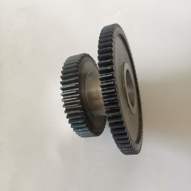
The Precision of Fly Cutter Tooth Profile Design: How Gearseiko Empowers High-End Worm Wheel Machining with Craftsmanship | Gearseiko
Introduction
In high-end precision power transmission systems, the meshing accuracy of worm and worm wheel pairs directly governs mechanical operating stability, load-bearing performance, noise level, and overall service life. As a flexible, low-cost, and high-efficiency forming process, fly cutter generative machining has become the preferred solution for single-piece customization, small-batch production, and large-module worm wheel manufacturing.
Many manufacturers overlook a core fact: the ultimate precision of fly cutter-machined worm wheels does not depend solely on machining parameters and equipment calibration, but fundamentally relies on scientific, customized fly cutter tooth profile design. As a professional high-precision gear manufacturing factory, Gearseiko thoroughly masters the conjugate motion principle between cutting tools and workpieces. We tailor fly cutter profiles for different worm types to eliminate theoretical profiling errors and deliver geometrically accurate, high-matching worm wheel products for high-end transmission equipment.
1. Core Generating Principle: Consistent Kinematics, Customized Profile Design
From the perspective of gear generating kinematics, the fly cutter shares the same theoretical working root as traditional worm wheel hobs. The fly cutter is essentially a single independent cutting tooth split from a complete worm hob. Its side cutting edges must fit perfectly on the helicoidal surface of the basic worm to simulate standard worm meshing motion and complete accurate tooth profile forming.
Nevertheless, one-size-fits-all fly cutter profiles cannot adapt to industrial diversified worm transmission structures. Different worm types feature distinct helical surface equations and section geometric characteristics. Only targeted profile design, tool surface positioning, and grinding schemes can eliminate meshing deviation, tooth surface distortion, and precision attenuation. This is the core technical secret of Gearseiko’s stable high-quality fly cutter machining.
2. ZN Normal Straight-Sided Worm: Linear Edge Matching & Simplified High-Precision Forming
The Normal Straight-Sided (ZN) worm is widely applied in standard precision worm gear pairs. For fly cutter machining of ZN-type worm wheels, the profile design logic is standardized and clear.
The fly cutter’s cutting edge adopts a strict linear structure, completely consistent with the normal section contour of the matched working worm. Its pressure angle is precisely equal to the worm’s normal pressure angle. During tool assembly and positioning, the fly cutter’s rake face must be accurately locked on the worm’s normal plane to form a standardized geometric meshing relationship.
This design scheme features simple calibration, stable forming, and zero theoretical profiling errors. With rich accumulated engineering data, Gearseiko’s technical team quickly completes parameter calculation, profile confirmation, and precision grinding according to customer ZN worm specifications, ensuring that each custom fly cutter perfectly restores the theoretical tooth profile and achieves optimal meshing performance of ZN worm gear pairs.
3. ZA Archimedean Worm: Lead Angle Classification & Differentiated Profile Optimization
Archimedean (ZA) worms are the most mainstream type in industrial transmission equipment, featuring strong universality but complex profile design requirements. The lead angle serves as the core classification standard for ZA fly cutter design, with completely different processing strategies for small and large lead angles.

3.1 Small Lead Angle (γ ≤ 5°): Axial Straight-Edge Simplified Design
When the worm lead angle is ≤ 5°, the helical surface distortion is negligible. The fly cutter rake face can be installed on the axial section of the cutter arbor, equivalent to a single-tooth straight-flute hob. Both side cutting edges maintain linear shapes, and the pressure angle matches the axial pressure angle of the ZA worm.
This scheme is simple to adjust, highly efficient, and stable in precision, fully meeting the machining requirements of most small and medium-module ZA worm wheels, and is the most cost-effective conventional processing solution.
3.2 Large Lead Angle (γ > 5°): Symmetrical Rake Angle Correction & Curved Profile Customization
When the lead angle exceeds 5°, the unilateral cutting resistance of the fly cutter increases sharply, resulting in obvious asymmetry in the cutting state of the two side edges. Ordinary axial straight-edge profiles will cause uneven tool wear, serious tooth surface distortion, and meshing jitter.
Professional heavy-duty solution for large modules: Gearseiko adopts special rake face grinding technology to balance the rake angles of the left and right cutting edges, ensuring consistent cutting performance on both sides and maintaining profile accuracy. This complex customized grinding process is specially used for high-value large-module worm wheel processing scenarios.
Optimized economical solution for small and medium modules: For small and medium-module workpieces, we abandon traditional axial installation and adopt normal plane positioning. Although this setup achieves zero rake angle symmetry, the tooth profile is no longer linear — it must fit the curved normal section profile of the ZA worm.
Gearseiko derives accurate normal section curve equations through professional helicoid coordinate transformation. Combined with high-precision wire EDM and CNC automatic programming technology, we complete full-point coordinate calculation, profile fitting, and ultra-precision grinding of the curved tooth profile. Whether based on customer design drawings or independent theoretical calculation, our fly cutters strictly control curve errors within micron-level tolerances, realizing true theoretical profile reduction.
4. Gearseiko’s Core Advantages in Fly Cutter Profile Precision Manufacturing
Fly cutter manufacturing seems structurally simple, but ultra-high precision is required in theoretical calculation, profile fitting, tool steel selection, and finish grinding. Slight deviations in any link will be amplified in worm wheel meshing operation, affecting the overall transmission performance.
Gearseiko builds full-process precision control systems for fly cutter customization: we select high-quality W18Cr4V high-speed tool steel with excellent wear resistance and rigidity; rely on professional gear tool theoretical algorithms to complete accurate profile modeling; adopt wire EDM for high-precision rough forming and multi-pass CNC finish grinding; and equipped with professional precision inspection equipment to conduct full-size error detection.
We always adhere to the essence of gear craftsmanship: precision originates from theoretical rigor, and stability comes from process standardization. By virtue of differentiated customized fly cutter profile design technology, we solve the common industry pain points of poor worm wheel meshing accuracy, unstable surface quality, and low wear resistance.

Conclusion
Fly cutter tooth profile design is the core foundational technology of high-end worm wheel fly cutting machining. Different ZN and ZA worm types require completely independent profile design and tool positioning schemes, and lead angle changes directly determine the rationality of the processing strategy.
Breaking the industry’s crude unified-profile processing mindset, Gearseiko relies on professional gear transmission theory, advanced processing equipment, and mature engineering experience to provide targeted fly cutter customization and precision worm wheel manufacturing services for diverse high-end transmission scenarios. From single-piece prototype customization to batch standardized production, we consistently deliver high-precision, high-stability, high-durability worm wheel solutions for global industrial equipment.
FAQ | Fly Cutter Tooth Profile Design & Worm Wheel Machining
Q1: Why customize fly cutter profiles for different worm types?
A1: ZN and ZA worms have different helical surface geometric equations. A unified fly cutter profile will cause theoretical profiling errors, resulting in distorted worm wheel tooth surfaces, poor meshing accuracy and unstable transmission operation. Customized design eliminates principle errors fundamentally.
Q2: What is the difference between ZN and ZA fly cutter profile design?
A2: ZN worm fly cutters adopt linear cutting edges matched with normal sections; ZA worm fly cutters are classified by lead angle, using linear axial profiles for small angles and optimized curved normal profiles for large angles to ensure cutting symmetry and profile accuracy.
Q3: What problems will large lead angle ZA worms face with ordinary fly cutters?
A3: When the lead angle exceeds 5°, ordinary straight-edge fly cutters cause asymmetric cutting resistance, uneven tool wear, obvious tooth profile distortion, and reduced transmission stability and service life.
Q4: How does Gearseiko ensure the precision of curved fly cutter profiles?
A4: We adopt professional helicoid coordinate transformation to derive accurate curve equations, match wire EDM forming and multi-pass CNC precision grinding, and conduct full-size tolerance detection to control profile errors within micron level.
Q5: What tool materials does Gearseiko use for custom fly cutters?
A5: We adopt high-quality W18Cr4V high-speed steel, which features high rigidity, high wear resistance and high-temperature resistance, ensuring long-term stable cutting performance and repeated regrinding accuracy of fly cutters.
Q6: Can customized fly cutters improve worm wheel meshing quality?
A6: Yes. Tailored profiles eliminate theoretical meshing deviations, optimize tooth surface contact patterns, reduce operating noise and friction, and significantly improve the precision stability and service life of worm gear transmission pairs.
How Gearseiko Sets New Standards in High End Worm Gear Machining
Precision Worm Gear Manufacturing on Universal Milling Machines
Related Article



