
Load Analysis and Calculation of Planetary Gear Transmission System
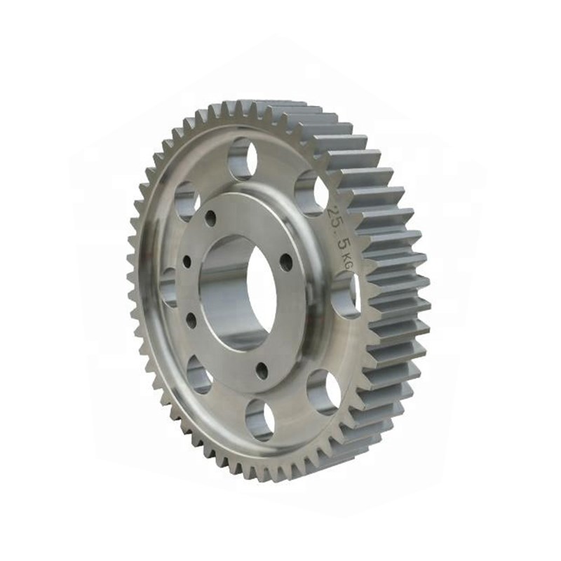
Advanced Load Analysis and Calculation of Planetary Gear Transmission Systems: Gearseiko Delivers Precision Engineering for Demanding Applications
Introduction
Planetary gear transmission systems have become the backbone of modern power transmission in heavy machinery, aerospace, automotive, and industrial automation. Their unique ability to combine high torque density with compact dimensions makes them indispensable for applications where space and weight are critical. However, the performance and reliability of a planetary drive depend heavily on accurate load analysis, proper handling of uneven load distribution (load sharing), and optimal design of load‑sharing mechanisms. At Gearseiko, we specialize in manufacturing high‑precision planetary gear components and fully assembled drive systems, integrating rigorous theoretical foundations with advanced production techniques to deliver superior performance, durability, and cost‑effectiveness.
1. Outstanding Advantages of Planetary Gear Transmissions
Planetary gear systems offer multiple advantages over traditional parallel‑axis or worm gear drives:
-
Small mass and compact volume – Power is split among several planet gears, allowing high torque transmission in a small envelope.
-
Large transmission ratios – Single‑stage ratios from 3:1 to 12:1 (and much higher in multi‑stage configurations).
-
High transmission efficiency – Typically 97–99% per stage, reducing energy loss.
-
Exceptional load‑carrying capacity – Multiple planet paths share the load, lowering stresses on individual gear teeth.
Because of these benefits, planetary drives are widely used in construction machinery, mining equipment, metallurgical plants, lifting and transport systems, light industry machinery, petrochemical installations, precision instruments, robotics, and wind turbines. They perform excellently both in high‑speed, high‑power conditions (e.g., turbine gearboxes) and low‑speed, high‑torque applications (e.g., tracked vehicle final drives). Today, planetary transmission technology is a key focus of global mechanical drive development, and Gearseiko is at the forefront of this evolution in China and beyond.
2. Addressing the Challenges: Gearseiko’s Advanced Manufacturing Approach
No technology is without drawbacks. Planetary gear transmissions traditionally face several challenges:
-
Stringent material requirements – Gears must withstand high contact and bending stresses; therefore, case‑hardened alloy steels (e.g., 18CrNiMo7‑6, 20MnCr5) are essential.
-
Complex structure – Sun gear, planet carrier, ring gear, and multiple planet gears require precise assembly.
-
Difficult manufacturing and assembly – Tight tolerances on gear geometry, carrier pin positions, and bearing fits are mandatory.
However, through deep research, international technology absorption, and continuous process improvement, the Chinese gear industry has made remarkable progress. Gearseiko has invested in state‑of‑the‑art CNC gear grinding machines (e.g., Reishauer, Kapp), advanced heat treatment lines (carburizing, nitriding), and coordinate measuring machines (CMM) for full inspection. Our production facility consistently achieves AGMA Class 12–14 precision levels. Practical experience demonstrates that even a medium‑skill gear factory can produce good planetary reducers, but Gearseiko goes further by implementing strict statistical process control (SPC) and 100% final testing, ensuring our products exceed international standards.

3. In‑Depth Load Analysis: Understanding the Load Sharing Factor Kβ
One of the most critical parameters in planetary gear design is the load sharing factor Kβ (also referred to as Kγ or uneven load distribution factor). This factor quantifies how unevenly the transmitted torque is distributed among the multiple planet gears. Ideally, if all planets carry equal load, Kβ = 1.0. In reality, due to manufacturing and assembly errors, Kβ typically ranges from 1.1 to 1.5 or even higher.
3.1 Factors Influencing Kβ
Based on Gearseiko’s extensive engineering database, the Kβ value depends on:
| Influencing Factor | Effect on Kβ |
|---|---|
| Manufacturing accuracy (gear tooth profile, lead, pitch; carrier pin position errors) | Higher accuracy → lower Kβ |
| Transmitted load magnitude | Higher load → lower Kβ (due to improved tooth contact under load) |
| Stiffness of supporting components (shafts, bearings, housing) | Higher stiffness → lower Kβ |
| Gear material and tooth surface hardness | Harder, smoother surfaces → lower Kβ after running‑in |
| Running‑in condition of tooth flanks | Good running‑in → lower Kβ |
| Gear meshing speed | Higher speed → higher Kβ (dynamic effects) |
| Number of planet wheels | More planets → higher Kβ (more error contributors) |
| Performance of load‑sharing mechanism | Effective mechanism → lower Kβ |
3.2 Practical Calculation Approach
In practice, the load sharing factor is determined through a combination of:
-
Elastic deformation analysis (finite element method or analytical models) considering sun gear, carrier, and ring gear deflections.
-
Monte Carlo simulation of manufacturing tolerances (tooth thickness variation, pin position errors, bearing clearances).
-
Experimental strain gauge or torque measurement on prototype gearboxes.
Gearseiko’s engineering team has developed proprietary calculation tools that integrate ISO 6336 and AGMA 6123 standards with specific correction factors derived from real‑world testing. For a typical 3‑planet system with AGMA Class 11 components, our analysis shows Kβ values between 1.15 and 1.25 at nominal load. By improving carrier pin position accuracy to within 10 μm and using flexible pins (a type of load‑sharing mechanism), we reduce Kβ to 1.05–1.10.
3.3 Design Recommendations to Minimize Kβ
Based on our experience, Gearseiko recommends:
-
Specify higher manufacturing precision for critical components (especially carrier and ring gear).
-
Apply controlled run‑in procedures (light load at moderate speed for several hours).
-
Use case‑carburized and ground gears with surface hardness of 58–62 HRC.
-
Avoid excessive planet numbers unless a sophisticated load‑sharing mechanism is employed.
-
For high‑speed applications (above 10 m/s pitch line velocity), consider floating sun gear or floating ring gear designs.
4. Load‑Sharing Mechanisms: Selection Principles and Gearseiko’s Best Practices
A well‑designed load‑sharing mechanism compensates for unavoidable manufacturing and assembly errors, thus reducing Kβ. However, it is crucial to understand that a load‑sharing mechanism cannot replace basic manufacturing accuracy. Excessively low precision will degrade the mechanism’s effectiveness, induce vibration and noise, and may ultimately cause transmission failure.
4.1 Common Types of Load‑Sharing Mechanisms
| Type | Working Principle | Typical Applications | Advantages | Disadvantages |
|---|---|---|---|---|
| Floating sun gear | Sun gear radially and/or axially floating | General industrial reducers | Simple, low cost | Limited compensation ability |
| Floating ring gear | Ring gear supported by elastic elements | High‑precision drives | Good compensation | Complex housing design |
| Flexible pins (planet carrier) | Each planet pin is slender and bends under load | Heavy‑duty mining gearboxes | Excellent load sharing | Requires careful stress analysis |
| Elastic bearing supports | Bearings with controlled clearance or preload | Aerospace, robotics | High dynamic response | Higher cost |
4.2 Gearseiko’s Selection Guidelines
When designing a planetary gearbox for a customer, Gearseiko follows these principles:
-
Keep the overall structure simple – Avoid over‑engineering; use floating elements only when necessary.
-
Ensure high service reliability – The mechanism must not introduce additional failure modes (e.g., fatigue of flexible pins).
-
Provide smooth and quiet operation – Minimize backlash variation and dynamic excitation.
-
Maximize load capacity and efficiency – Any friction or parasitic loss must be negligible.
-
Control production and maintenance costs – Choose mechanisms that are manufacturable with our existing precision capabilities.
For example, in a recent project for a construction machinery manufacturer (track drive for 30‑ton excavators), Gearseiko selected a floating sun gear combined with crowned planet gear teeth. The sun gear is allowed to float radially by 0.2–0.3 mm, automatically centering itself under load. Post‑production testing showed a Kβ reduction from 1.28 (without float) to 1.09 (with float), and gearbox life increased by 35%.
4.3 Common Pitfalls to Avoid
-
Using a floating mechanism as a crutch for poor manufacturing – This leads to unstable load sharing and premature wear.
-
Ignoring dynamic effects – At high speeds, floating elements may become unstable (whirl).
-
Over‑constraining the system – For example, using both a floating sun and a floating ring gear simultaneously can create redundant constraints.
Gearseiko’s design review process systematically checks for these issues, ensuring robust and reliable operation under all specified load and speed conditions.

5. Kinematic Analysis: The Foundation of Reliability Prediction
A thorough kinematic analysis is essential before any load or stress calculation. For a planetary gear train, the fundamental kinematic equation is:
where:
-
nsns = sun gear speed
-
nrnr = ring gear speed
-
ncnc = carrier speed
-
kk = ratio of ring gear teeth to sun gear teeth (Zr/ZsZr/Zs)
From this equation, we can derive speed ratios for all possible operating modes (sun input – carrier output, ring fixed – carrier output, etc.). Gearseiko uses this relationship together with torque balance equations to compute individual gear mesh loads, which then feed into tooth bending and contact stress calculations (according to ISO 6336 or AGMA 2001).
Accurate kinematic modeling also allows us to predict the influence of manufacturing tolerances on relative tooth phasing, which affects vibration excitation (transmission error). By controlling the tooth indexing and lead accuracy, Gearseiko reduces transmission error by up to 30% compared to standard commercial grades, directly improving noise, vibration, and harshness (NVH) performance.
6. Case Study: Gearseiko Optimizes a Wind Turbine Planetary Stage
To illustrate our integrated approach, consider a 3‑MW wind turbine gearbox high‑speed planetary stage. The customer required:
-
Input power: 3,000 kW
-
Input speed: 1,500 rpm
-
Ratio: 5.5:1
-
Number of planets: 4
Initial design (competitor’s product) suffered from high Kβ (1.42) leading to premature planet bearing failures. Gearseiko performed the following steps:
-
Load analysis – Using finite element analysis, we identified excessive carrier pin position errors (±35 μm) as the main cause.
-
Redesign of carrier – We changed to a welded steel carrier with precision boring on a 5‑axis machining center, achieving pin position tolerances of ±10 μm.
-
Selection of load‑sharing mechanism – A floating sun gear (radial clearance 0.25 mm) was adopted, and planet gear teeth were modified with a 10 μm crown to accommodate angular misalignments.
-
Manufacturing and testing – All gears were ground to AGMA Class 13. The assembled gearbox was tested on a back‑to‑back test rig with torque measurement on each planet pin.
Results:
-
Measured Kβ = 1.09 at nominal load
-
Bearing life increased from 45,000 hours to over 80,000 hours (calculated)
-
Noise level reduced by 4 dB(A)
-
The customer has since placed repeat orders for 50+ units.
7. Gearseiko’s Technical Commitment to Global Customers
As a specialized manufacturer of high‑end precision gears and planetary drive systems, Gearseiko offers:
-
Engineering support – Free initial load analysis and Kβ estimation for your application.
-
Custom manufacturing – Sun gears, planet gears, ring gears, and complete carriers up to 1,200 mm diameter.
-
Quality assurance – 100% gear inspection (tooth profile, lead, pitch, runout) and optional magnetic particle or ultrasonic testing.
-
Short lead times – Rapid prototyping available (4–6 weeks) thanks to flexible production cells.
We understand that every application has unique demands – whether it is ultra‑low backlash for robotics (≤1 arcmin), high reliability for mining (50,000‑hour design life), or cost‑effectiveness for automotive transmissions. Our team will work with you to select the optimal load‑sharing mechanism, manufacturing precision level, and gear geometry to achieve the best balance of performance, durability, and price.
Conclusion
Planetary gear transmission systems offer unparalleled advantages in power density and efficiency, but their successful application depends on a deep understanding of load distribution, accurate calculation of the load sharing factor Kβ, and proper design of load‑sharing mechanisms. Gearseiko combines theoretical rigor – from kinematic equations to finite element analysis – with world‑class manufacturing capabilities to deliver planetary drives that set new standards for reliability and performance. Whether you need standard components or a fully custom engineered solution, Gearseiko is your trusted partner in precision gearing.
Contact Gearseiko today to discuss your planetary gear requirements and let our experts optimize your drive system for maximum load capacity and service life.
Analysis and Calculation of the Partial Load Behavior of Helicopter Planetary Gear Transmission System
Principles for Selecting the Balanced Load Mechanism
Related Article



