
Analysis of Gear Failure Mechanism
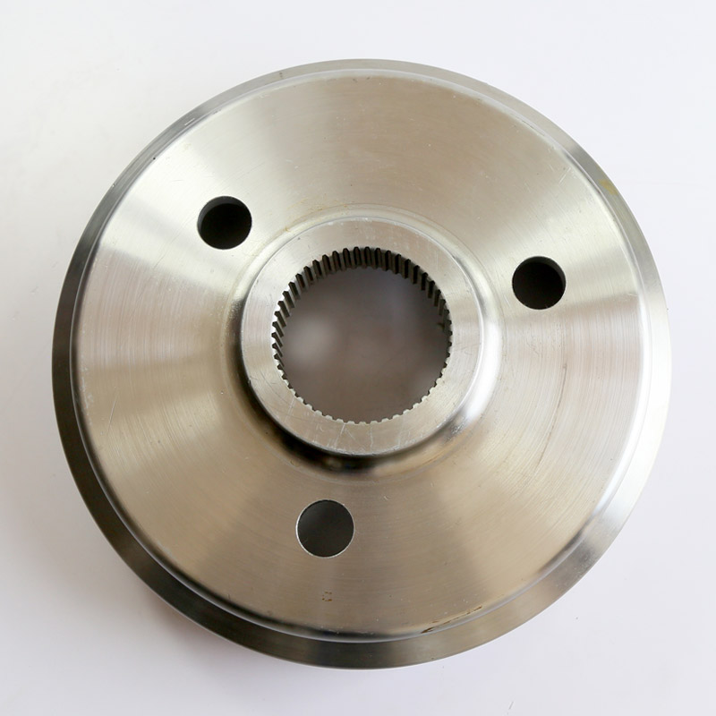
Bending Fatigue Fracture Mechanism of High-Precision Gears and Prevention Strategies – Professional Analysis by Gearseiko
In modern power transmission systems, gears are core components whose reliability and service life directly affect the operational safety of complete equipment. Among various gear failure modes, bending fatigue fracture of gear teeth is widely recognized as the most dangerous failure mode due to its sudden onset and catastrophic consequences. Gearseiko, a specialist in high-precision gear manufacturing, has long been committed to in-depth research on gear failure mechanisms, aiming to improve bending fatigue resistance through optimized design, material selection, and process control. This article provides a professional analysis of the occurrence pattern, mechanical essence, and crack evolution process of gear tooth bending fatigue fracture, offering valuable insights for enhancing transmission system reliability.
1. Propagation Characteristics and Hazards of Bending Fatigue Fracture
Bending fatigue fracture of gear teeth is rarely an isolated event. Under cyclic loading, fatigue cracks typically initiate and propagate on a specific tooth first. When that tooth fractures instantaneously because the remaining cross-section can no longer withstand the external load, the load originally carried by that tooth is immediately transferred to the adjacent teeth. Since the design load margin of adjacent teeth is limited, the additional load accelerates their fatigue damage accumulation, leading to successive fractures of the second and third teeth. This process is accompanied by a stepwise amplification of impact energy, causing the failure propagation rate to increase exponentially and potentially resulting in complete destruction of the entire gear. Gearseiko has found in numerous failure case analyses that understanding the failure mechanism and fracture pattern of the first fractured tooth is the key to interrupting this chain reaction.
2. Mechanical Nature of Root Stress Distribution and Crack Initiation
When a pair of gear teeth come into mesh, the contact load at the tooth flank generates a complex stress distribution at the tooth root. Accurate finite element analysis and photoelastic tests have confirmed that: the maximum tensile stress occurs on the tooth root surface of the loaded flank – this is the weakest point when the tooth is subjected to bending load; while the maximum compressive stress occurs on the tooth root surface of the opposite (unloaded) flank. Below the intersection of the tooth centerline and the root circle, there exists a theoretical zero‑stress point.
Due to the geometric discontinuity (transition fillet) at the tooth root, stress concentration is highly significant. Depending on the tooth profile parameters, fillet radius, and load application point, the stress concentration factor at the root of the loaded flank can vary from 1.4 to 2.5. This means that when the nominal bending stress is only 200 MPa, the local peak stress may already reach 500 MPa, far exceeding the material’s fatigue limit. Therefore, under cyclic loading, this region becomes the most preferential site for fatigue crack initiation. Gearseiko, in its gear design, effectively reduces the stress concentration factor and minimizes crack initiation risk by optimizing the tooth root fillet radius and applying processes such as root shot peening.

3. Crack Propagation Path and Fracture Surface Morphology
Once a microcrack initiates on the tooth root surface of the loaded flank, it propagates along the direction of the maximum principal stress toward the zero‑stress point. As the crack length increases, the neutral axis of the remaining load‑bearing cross‑section shifts, and the original zero‑stress point moves dynamically downward toward the root of the unloaded flank. This process follows the law of stable crack growth in fracture mechanics, where the crack growth rate is closely related to the stress intensity factor range.
When the crack extends to a critical size, the net cross‑section of the remaining material can no longer sustain the external load, and the tooth fractures in a brittle manner within milliseconds. Two typical regions can be clearly distinguished on the macroscopic fracture surface:
-
Crack propagation zone: smooth, flat, often with beach‑mark fatigue striations, appearing dull grey – this is the trace of slow fatigue crack growth.
-
Instantaneous fracture zone: rough, with a metallic luster and evident ductile tearing features (such as shear lips), reflecting the rapid overload fracture at final failure.
This composite fracture morphology (smooth zone + rough zone) is a typical signature of bending fatigue failure. Gearseiko’s failure analysis laboratory is equipped with high‑magnification microscopes and scanning electron microscopes to accurately identify fracture characteristics and provide customers with precise root‑cause diagnosis.
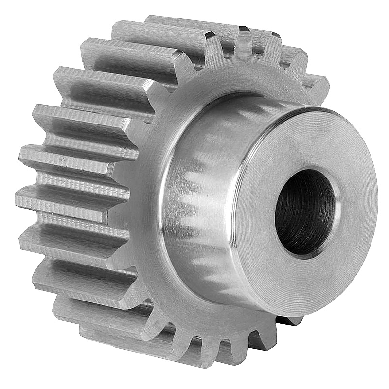
4. Chain Failure Mechanism After the First Tooth Fracture
The occurrence of the first fractured tooth not only means the failure of a single component but also fundamentally alters the dynamic behavior of the entire gear pair. The actual tooth profile of the fractured tooth separates from the theoretical tooth profile, redistributing the meshing forces that were originally evenly shared among multiple teeth. The two adjacent teeth will bear additional loads far exceeding their design values, potentially increasing their bending stress level by 30% to 50% instantly. At the same time, the impact excitation generated by the fracture excites the natural vibration modes of the gear pair, leading to a significant increase in vibration acceleration level, worsening meshing noise, and sharply reducing transmission smoothness and operational reliability.
What is more serious is that the adjacent teeth under high stress will enter the stages of fatigue crack initiation and propagation at a much faster rate, thus forming a positive feedback loop of “tooth fracture – load redistribution – accelerated fatigue – another tooth fracture”. Gearseiko’s experience shows that if the system is not shut down for inspection promptly after the first tooth fracture, the entire gear may become completely ineffective within a few hours.
5. Gearseiko’s Anti‑Fatigue Design and Solutions
Based on a deep understanding of the bending fatigue fracture mechanism, Gearseiko implements the following core strategies in the manufacturing of high‑precision gears:
-
Optimized tooth root geometry: large‑radius fillet design combined with finite element optimization to keep the stress concentration factor below 1.6.
-
High‑cleanliness materials: use of vacuum degassed or electroslag remelted alloy steels to reduce non‑metallic inclusions and other crack sources.
-
Surface integrity processes: tooth root shot peening plus grinding/polishing to introduce a beneficial compressive residual stress layer that effectively prevents crack initiation.
-
Full‑inspection system: magnetic particle inspection and residual stress testing at the tooth root for every batch, ensuring zero‑defect delivery.
Through these technical measures, Gearseiko precision gears achieve bending fatigue life 2 to 3 times higher than industry standards under cyclic heavy‑load conditions, providing reliable transmission solutions for customers in wind power, aerospace, high‑end machine tools, and new energy vehicles.
For further information on gear failure analysis or custom anti‑fatigue gear solutions, please contact the Gearseiko technical team. We are ready to provide professional engineering support.
This article is based on Gearseiko’s proprietary knowledge and practical experience in gear failure analysis.
Rolling contact fatigue of gears
Analysis of Gear Load Characteristics and Influencing Factors of Load
Related Article



