
Solutions and Precision Gear Solutions from Gearseiko
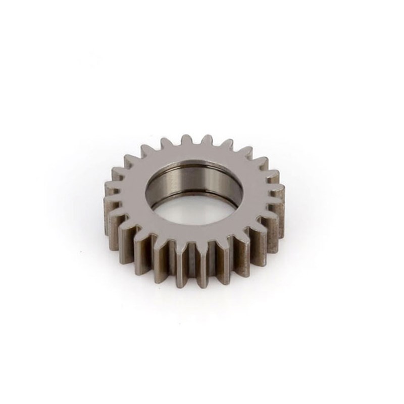
Mastering Fly Tool Machining: Defects, Solutions, and Precision Gear Solutions from Gearseiko | Gearseiko
Introduction
Within high-precision worm gear manufacturing, fly tool generating machining remains an irreplaceable flexible process, especially suitable for single replacement parts, prototype trial production and small-batch customized worm gear processing. When custom dedicated worm hobs come with exorbitant costs and long delivery lead times, fly tools become the most economical and feasible alternative for low-volume orders.
Nevertheless, fly tool machining carries inherent geometric principle errors originating from its unique tangential feed kinematics. Without systematic theoretical control and standardized process calibration, various tooth surface defects will emerge and severely degrade transmission performance, meshing stability and service life of finished worm gear pairs.
As a professional manufacturer focused on high-end precision gear fabrication, Gearseiko has accumulated abundant on-site production experience in fly tool machining defect diagnosis and correction. This article systematically analyzes the root cause of core inherent errors in fly tool processing, elaborates typical tooth profile & contact zone defects, and delivers targeted, operable optimization solutions to help manufacturers stabilize worm gear machining quality and achieve ideal meshing contact performance.
1. Root Source of Defects: Inherent Principle Errors of Fly Tool Generating Motion
The fundamental quality gap between hobbed worm gears and fly tool machined worm gears stems from distinct tool-workpiece relative motion trajectories, which lead to irreducible geometric deviations.
1.1 Kinematic Difference Between Standard Hob and Fly Tool
When a dedicated integral worm hob cuts a worm gear, the hob spindle axis maintains a fixed perpendicular relationship with the worm gear blank axis during the full generating cycle. The generatrix of the formed tooth root cylindrical surface is a perfect circular arc whose radius equals the hob tip radius, delivering standard theoretical tooth geometry without inherent profile distortion.
In contrast, fly tool machining adopts tangential axial feed movement. The cutter arbor axis tilts by an angle equal to the workpiece’s helix angle relative to the worm gear blank axis. This structural difference completely changes the tooth root surface forming trajectory: the generatrix of the tooth root cylinder transforms from a standard circular arc into an elliptical curve.
1.2 Derived Typical Geometric Defects
In addition to elliptical tooth root distortion, the fly tool’s discrete single-tooth cutting path creates inconsistent cutting depth along the full tooth height, triggering two prominent measurable defects:
- Variable tooth space width If actual cutting depth exceeds theoretical value, tooth space will be excessively wide; insufficient cutting depth results in narrowed tooth space, disrupting uniform tooth thickness distribution around the gear circumference.
- Tooth trace offset deviation Gradual deepening cutting depth shifts the tooth trace toward the gear tooth body center; reduced cutting depth pulls the tooth trace toward the tooth gap center. Uneven tooth traces cause unstable meshing, increased transmission noise and local concentrated wear.
Key core conclusion: No matter how the fly tool reference circle radius is adjusted, fly tool machining cannot fully replicate the standard geometric tooth surface produced by a dedicated worm hob. Production control targets should focus on restraining, compensating and optimizing geometric deviations to match actual application requirements, rather than pursuing complete elimination of inherent principle errors.

2. Contact Zone: The Core Criterion for Evaluating Worm Gear Meshing Quality
The meshing contact zone is the most intuitive and critical inspection index for worm gear transmission performance. Improper contact zone size, position or shape will directly trigger multiple failure risks: local heavy load pitting, abnormal operation noise, periodic vibration and even early fatigue fracture of tooth flanks.
Gearseiko summarizes a clear universal rule verified by massive production data:
- Reducing fly tool reference circle diameter → contact zone expands and extends toward both sides of the gear throat
- Increasing fly tool reference circle diameter → contact zone shrinks and concentrates around the central throat area
This quantitative correspondence serves as the core theoretical basis for contact zone correction and process optimization.
3. Differentiated Optimization Solutions for Ideal Contact Zone
We classify worm gears into power transmission type and motion transmission type, and formulate targeted fly tool parameter matching standards according to different load and precision demands:
3.1 Heavy-Duty Power Transmission Worm Gears
Sufficient contact area is mandatory to evenly disperse bearing load and avoid local stress concentration. Too small contact range will cause rapid tooth surface pitting, abrasion and shortened service life under continuous heavy load operation.
3.2 Light-Load Motion Transmission Worm Gears
Oversized contact area is unnecessary and often signals over-cutting during fly tool processing, which aggravates tooth trace deviation, tooth width error and other geometric defects, sacrificing motion accuracy for redundant contact range.
3.3 Universal Standard Contact Zone Specification
For most general industrial transmission scenarios, the optimal contact zone shall occupy 1/2 ~ 3/4 of the central tooth face width, with reasonable non-contact buffer sections reserved at both tooth inlet and outlet ends. This layout ensures smooth gradual engagement and disengagement of the worm and worm gear teeth, while maintaining stable uniform load bearing during the full meshing cycle.
3.4 Special Parameter Matching Rules
Two key workpiece parameters determine the selection of fly tool reference circle diameter:
- When the worm gear tooth wrap angle is small or helix angle is large: Adopt fly tool with larger reference circle diameter to concentrate contact zone at the gear throat
- When the worm gear tooth wrap angle is large or helix angle is small: Adopt fly tool with smaller reference circle diameter to expand contact coverage
3.5 On-Site Fine-Tuning Correction Method
If post-machining contact zone shape and size deviate from design expectations, adjust the fly tool reference circle diameter as the primary correction measure. Minor backlash increase is a predictable side effect of this adjustment, yet the significant improvement in meshing smoothness and contact uniformity far outweighs this minor trade-off in over 90% of industrial applications.
4. Gearseiko’s Comprehensive Technical Advantages in Fly Tool Machining
Unlike manufacturers that only conduct passive post-process defect correction, Gearseiko builds a full-cycle precision control system covering pre-production theoretical simulation, customized tool design and finished product inspection:
- Forward geometric simulation analysis: Calculate theoretical contact zone distribution before formal cutting to predict potential defects and optimize fly tool parameters in advance
- Customized fly tool design: Match exclusive reference circle diameter, tooth profile and installation angle according to each customer’s workpiece module, helix angle, load condition and application type
- Full-process rigorous quality inspection: Detect tooth thickness, tooth trace, tooth root profile and contact zone shape after trial cutting, and implement real-time parameter fine-tuning
- Rich cross-industry application experience: Mature processing schemes for both heavy power transmission and high-precision motion control worm gear equipment
Whether you need single-piece replacement worm gear processing or small-batch standardized production optimization, Gearseiko’s professional technical team can eliminate fly tool machining defects, calibrate ideal contact zone geometry and extend the overall service life of your worm gear transmission sets.

Conclusion
Fly tool machining’s inherent elliptical tooth root principle error inevitably brings variable tooth space width and tooth trace offset defects, which directly determine the final meshing contact zone performance of worm gear pairs. Instead of blindly pursuing zero geometric deviation, manufacturers should adopt differentiated fly tool diameter matching strategies based on actual transmission load, helix angle and tooth wrap angle parameters.
Through pre-simulation theoretical prediction, customized fly tool design and post-processing contact zone calibration, Gearseiko effectively restrains various fly tool machining defects and delivers stable, low-noise, long-service-life precision worm gears for global mining, automation, heavy machinery and general transmission industries.
FAQ | Fly Tool Machining Defects & Contact Zone Optimization
Q1: Why cannot fly tool machining fully replace dedicated worm hob processing?
A1: Fly tool tangential feed creates elliptical tooth root generatrix instead of the perfect circular arc formed by standard hobs, bringing inherent tooth trace and tooth width variation errors that cannot be completely eliminated, while integral hobs have no such principle geometric deviations.
Q2: How does fly tool diameter affect worm gear meshing contact zone?
A2: Smaller fly tool reference circle diameter widens contact zone toward two sides of the throat; larger fly tool diameter gathers contact area at the gear central throat, which is the core adjustment method for contact zone correction.
Q3: What is the standard ideal contact zone range for ordinary worm gears?
A3: The optimal contact zone accounts for 1/2 to 3/4 of central tooth face width, with proper buffer non-contact areas at tooth inlet and outlet ends for smooth meshing transition.
Q4: When should we choose a larger fly tool reference circle diameter?
A4: It is recommended for worm gears with small tooth wrap angle or large helix angle to concentrate contact area at the gear throat and avoid excessive edge contact wear.
Q5: What are the typical defects caused by fly tool principle errors?
A5: Two main measurable defects: variable tooth space width caused by inconsistent cutting depth, and tooth trace offset shifting toward tooth body or tooth gap center with changing cutting depth.
Q6: What core advantages does Gearseiko have in fly tool machining quality control?
A6: We conduct pre-cut geometric simulation prediction, customize fly tool parameters per workpiece specifications, carry out full-item inspection after trial cutting, and own mature process schemes for both heavy power transmission and precision motion transmission worm gears.
Mastering Pitch Deviation and Helix Deviation in High End Gear Manufacturing
How Gearseiko Sets New Standards in High End Worm Gear Machining
Related Article



