
Proper Installation of Gear Blanks and Fixtures
author: Cash
2026-06-11
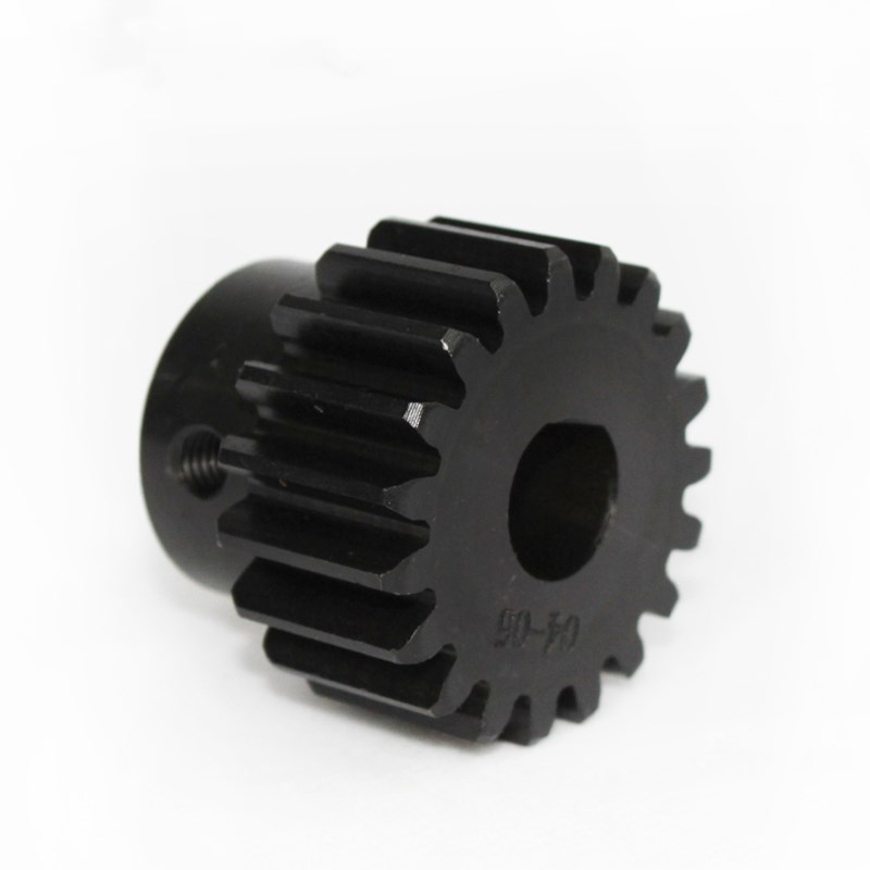
The Core Craft of Precision Gear Manufacturing: Proper Installation of Gear Blanks and Fixtures | Gearseiko
In high-precision gear production, the hobbing process defines the final quality grade of finished gears. Among all procedures, the installation of gear blanks and fixtures is a fundamental yet easily overlooked key step. As a professional manufacturer of high-end precision gears, Gearseiko recognizes that even micron-level deviations will lead to unacceptable vibration and noise in the final transmission system.
Today we share industry-best practices for installing gear blanks and fixtures, helping engineers avoid common mistakes and improve the consistency and accuracy of gear machining.
Fixture Installation: Precision Originates from Datum Surfaces
Fixture installation is the starting point of the whole process chain. Gearseiko’s standard operating rules require strict inspection of two core indicators: axial runout of the locating end face and radial runout of the locating arbor.
It is a wrong practice to pad the fixture base with paper or copper strips when axial runout exceeds the tolerance. The correct solution is to mount a turning attachment on the hob head and re-machine the locating end face to fix the deviation. Only by correcting errors on the datum surface can stable and repeatable positioning accuracy be guaranteed for mass production.
Surface Cleaning & Full Contact: Indispensable Details
Before mounting gear blanks, fully inspect and clean all locating surfaces of fixtures and blanks. Tiny burrs or foreign particles will cause positioning misalignment. On our production lines, workers use oilstones to remove protrusions and wipe surfaces thoroughly with clean cloths.
Follow this strict rule: the datum face of the gear blank must fit closely against the fixture’s locating end face. Do not place any paper or copper strips in between. Foreign objects will break full surface contact, trigger micro-displacement during machining, and eventually result in excessive cumulative pitch error.
Support & Clamping: Ensure Structural Stability
Arrange fixture support points as close to the cutting force acting area as possible. Optimally, place supports under the gear rim near the root circle. This reduces bending moment generated by cutting forces and lowers the risk of workpiece deformation.
Clamping must be firm and reliable, yet over-tightening is prohibited. Excess clamping force will cause elastic deformation on thin-walled or disc-shaped gear blanks. After unclamping, spring-back deformation will make the machined tooth profile deviate from the theoretical dimension. Gearseiko uses torque wrenches to control clamping force precisely, keeping consistent stress on every workpiece.
When tapping blanks to adjust runout, use copper hammers or hammers with copper heads. Never strike the workpiece while clamping bolts are fully tightened, to prevent hidden damage.
Special Installation Rules for Gear Shafts
Clamping solutions for gear shafts are classified by module size:
- Module m < 14 mm: Put copper strips between clamping jaws and shaft journals to protect finished surfaces from crushing.
- 14 mm ≤ m < 20 mm: Reserve machining allowance on clamped journals and keep the surface rough. Do not use copper strips, to ensure sufficient friction for clamping.
- m ≥ 20 mm: Subject to heavy cutting force. Leave stock on clamped journals and mill flat surfaces. Clamp directly on the flats to prevent shaft rotation during machining.
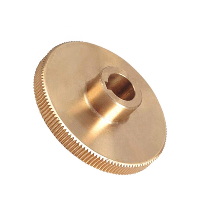
For gear shafts using collet fixtures, adopt copper-tipped clamping screws to avoid dents and scratches on finished surfaces.
Alignment & Runout Tolerance Control
Align gear shafts via the datum journals at both ends; align disc gears via the datum end face and auxiliary process references. Pay special attention to the phase of radial runout:
- If radial runout of two datum journals (or one journal plus auxiliary reference) is in phase: Total allowable error \(E \le F_r/2\) (\(F_r\) = gear radial runout tolerance).
- If the two runout values are 180° out of phase: The sum of both values must comply with stricter tolerance limits.
Conclusion
Precision gear manufacturing is a continuous effort to eliminate micron-level errors. Though blank and fixture installation looks basic, it determines the overall rigidity, stability and repeatability of the entire machining system. Gearseiko integrates all above specifications into standard work instructions. Regular skill training and on-site audits ensure every operator masters these key points proficiently.
If you are troubled by unstable machining accuracy, excessive radial runout after hobbing and other quality issues, feel free to contact our technical team. We supply high-end precision gears and share more than 20 years of practical process experience, helping you lift gear manufacturing precision to a higher level.
Gearseiko – Precision transmission begins with the perfect installation of every detail.
FAQ | Gear Blank & Fixture Installation Specifications
Q1: What is the correct way to fix excessive axial runout of fixture locating face?
A1: Re-machine the locating end face with a turning device instead of padding with paper or copper strips.
Q2: Why are paper and copper strips forbidden between blank and fixture datum faces?
A2: They break full surface contact, cause micro-movement and lead to large cumulative pitch error.
Q3: What risk does excessive clamping force bring to gear blanks?
A3: It causes elastic deformation; after unclamping, spring-back will distort the machined tooth profile.
Q4: How to protect finished journals when clamping small-module gear shafts?
A4: Place copper strips between clamping jaws and shaft journals.
Q5: What tolerance rule applies when two datum runouts are in phase?
A5: The total allowable error shall not exceed half of the gear radial runout tolerance \(F_r\).
A Precision Solution for Enhanced Tooth Strength
A Critical Step You Cannot Ignore in Precision Gear Manufacturing
Related Article



