
Precision Requirements for Hob Arbor and Hob Installation A Guide from Gearseiko
author: Cash
2026-06-09
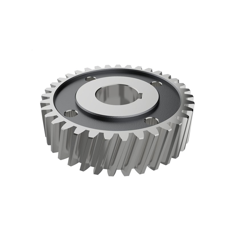
Precision Requirements for Hob Arbor and Hob Installation – A Guide from Gearseiko | Gearseiko
In high-end gear manufacturing, hobbing accuracy is the core determinant of final gear quality. The design of hob arbors and standard hob installation procedures are often underestimated, yet they exert a profound influence on overall machining precision. As a dedicated manufacturer of high-precision gears, Gearseiko recognizes that even premium gear hobs fail to deliver qualified products if paired with improper arbors or installed incorrectly. This guide elaborates on critical technical specifications for hob arbors and installation workflows, delivering practical references for gear processing professionals.
1. Hob Arbor: Prioritize Rigidity with Minimal Length
The hob arbor acts as the connecting component between the gear hob and hobbing machine, and its rigidity governs cutting stability. Production practice proves that the arbor should be kept as short as possible. Each additional millimeter of overhang leads to exponential growth in bending deformation. Meanwhile, the span between two bearing supports shall also be minimized within structural limits.
A short arbor with a narrow bearing span greatly enhances system rigidity, restrains cutting vibration effectively and guarantees superior tooth profile accuracy.
Material and precision requirements for qualified arbors:
- Made of high-strength alloy steel, fully quenched and tempered, and precision ground
- Surface roughness: Ra below 0.4 μm
- Cylindricity error: ≤ 2 μm
Only arbors meeting the above standards can provide a stable positioning reference for gear hobs.
2. Hob-Arbor Fit: Micron-Level Clearance & Hand-Push Assembly
The fit clearance between the hob bore and arbor is the most delicate part of installation. The standard clearance is controlled at 3–8 μm, avoiding excessive gap or zero interference.
Practical assembly criterion
After applying a thin layer of lubricant, operators can slide the hob onto the arbor smoothly with palm force only. There is no obvious resistance, and the hob will not slip off freely by itself. This clearance facilitates easy assembly and eliminates relative displacement or vibration under cutting loads.
Forbidden operation & correct steps
Never install the hob by hammering or impact. Impact force causes irreversible micro-bending deformation of the arbor and damages its straightness and runout precision.
- Thoroughly clean the arbor surface and hob bore, and remove all burrs and tiny particles
- Rotate the hob gently while pushing it onto the arbor
- Stop operation and check for scratches or debris on mating surfaces if jamming occurs; do not force assembly

3. Key & Keyway: Full Contact on Driving Flank
Torque is transmitted via the key and keyway assembly, whose fit accuracy directly affects uniform distribution of cutting force. Before tightening the locknut, ensure the driving flank of the key makes complete contact with the matching flank of the hob keyway without gaps.
Gearseiko’s assembly standards:
- Minimum contact area: 80%
- A 0.02 mm feeler gauge cannot be inserted into the contact gap
After securing the locknut, conduct runout inspection near the hob pitch circle:
- General gears: Radial runout and axial runout ≤ 0.01 mm
- High-precision gears: Radial runout and axial runout ≤ 0.005 mm
4. Spacer Washer & Locknut: Precision for Reliable Assembly
Spacer washers and locknuts are easily neglected accessories, while their manufacturing precision decides the overall assembly reliability.
Spacer Washer Requirements
- Parallelism error of two end faces: ≤ 0.003 mm
- Surface roughness: Ra ≤ 0.8 μm
- Complete quenching and tempering treatment to ensure dimensional stability
- When the bore-to-arbor clearance ≤ 0.005 mm, perpendicularity between end face and bore axis ≤ 0.005 mm
All washers are processed by double-end precision grinders and inspected one by one. Non-conforming parts are rejected before assembly.
Locknut Requirements
- Perpendicularity between nut end face and arbor axis after installation: ≤ 0.01 mm
- End face surface roughness: Ra ≤ 1.6 μm
Uneven end faces will tilt the hob and washer during tightening and ruin the hob’s installed runout. We recommend using precision-ground locknuts and testing end face runout with a dial indicator before every installation.
5. Overall Installation Principle: Short, Stout & Compact Supports
Follow the short and stout design principle for hob arbors: minimize overall length and adopt a reasonably large diameter. Keep the span between two bearing supports as narrow as possible.
For gears with module 2–6 mm, Gearseiko controls the arbor length-diameter ratio within 5:1.
Set moderate preload for the locknut: tight enough to prevent loosening during cutting, yet not overly tense to avoid tensile deformation of the arbor. After full assembly, test runout at four different circumferential positions of the hob with a 0.01 mm dial indicator. Start hobbing only after all measured data meet standards.

Conclusion
Hob arbor matching and installation are not simple manual work, but a systematic project requiring strict micron-level precision control. Gearseiko takes this procedure as a key quality control point in high-precision gear manufacturing, establishing complete internal standards covering arbor design, fit clearance selection, as well as precision machining and inspection of washers and locknuts.
We firmly believe that rigorous control over every installation detail is the foundation for stably producing high-end precision gears compliant with DIN Class 5 and higher accuracy grades.
If you are seeking a gear manufacturer that adheres to stringent technical specifications, feel free to contact Gearseiko. We deliver premium gear products and share mature precision machining know-how, helping global clients elevate their gear manufacturing capabilities.
FAQ | Hob Arbor & Installation Precision Standards
Q1: Why should the hob arbor be designed short?
A1: A shorter arbor improves overall rigidity, reduces bending deformation and suppresses cutting vibration effectively.
Q2: What is the standard fit clearance between hob bore and arbor?
A2: The clearance is controlled at 3–8 μm, allowing smooth hand-push assembly without free sliding.
Q3: What are the requirements for key and keyway assembly?
A3: The driving flank must achieve over 80% contact area; runout near the pitch circle shall be within 0.005–0.01 mm.
Q4: What precision indexes are required for spacer washers?
A4: End face parallelism ≤ 0.003 mm, with heat treatment for stable dimensions and qualified perpendicularity.
Q5: What is the recommended length-diameter ratio for common arbors?
A5: For module 2–6 mm gears, the arbor length-diameter ratio is controlled within 5:1.
How to Choose Cutting Parameters Scientifically? Insights from Gearseiko
How Gearseiko Restores Micro-Level Accuracy for High End Gear Manufacturing
Related Article



