
Key Steps by Gearseiko to Enhance Gear Machining Accuracy
author: Cash
2026-06-08
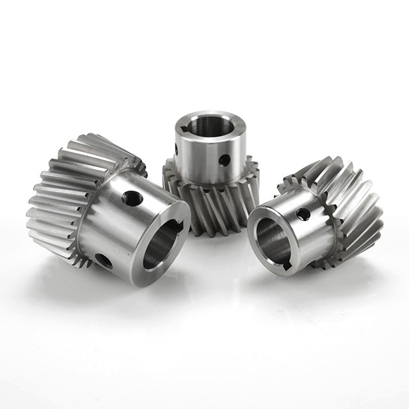
Precision Gear Blank Mounting Requirements: Key Steps by Gearseiko to Enhance Gear Machining Accuracy | Gearseiko
For high-end precision gear manufacturing, the mounting precision of gear blanks acts as a decisive factor for finished gear quality. Gears applied in aerospace, new energy vehicles, industrial robot drive systems and other premium sectors all demand rigorous mounting standards from the initial processing stage. As a professional manufacturer of high-end precision gears, Gearseiko regards standardized mounting of gear blanks and fixtures as a core procedure to guarantee overall machining accuracy.
This article elaborates on essential gear blank mounting specifications and standardized operating steps, helping industry practitioners boost the consistency and operational reliability of gear production.Contact Gearseiko’s technical team for professional guidance on gear blank clamping and customized precision gear manufacturing solutions.
1. Pre-Mounting Inspection & Surface Cleaning
Prior to installation, conduct full inspection on locating surfaces of both fixtures and gear blanks. In line with Gearseiko’s process regulations, operators need to check thoroughly for burrs, protrusions and foreign contaminants. Any burrs must be polished smooth with an oilstone. Afterwards, wipe all locating surfaces completely clean to eliminate dust, oil stains and tiny particles. Though seemingly simple, this step effectively blocks cumulative machining errors from the very start.
2. Full Contact of Datum Surfaces
The workpiece datum surface must be closely attached to the fixture locating face. Gearseiko strictly forbids placing paper gaskets, copper shims or other fillers between the two contact surfaces. Interlayer materials will trigger micro displacement and structural deformation under clamping force, undermining positioning stability and repeatability, and eventually leading to tooth profile deviation. Only direct metal-to-metal contact can realize accurate and stable datum transfer.
3. Optimize Support Positions
Arrange fixture supporting surfaces as close as possible to the points where cutting force is applied. Based on abundant on-site experience, placing supports at the rim near the root circle delivers the best performance to counteract bending moment and vibration generated during cutting. Reasonable layout improves overall machining rigidity, reduces elastic deformation of gear blanks under cutting load, and secures high-precision tooth profiles.
4. Standard Alignment Operations
Use copper hammers or hammers with copper heads for position adjustment. Gearseiko explicitly prohibits hard striking after clamping bolts are fully tightened, which may cause abnormal stress concentration on workpieces or damage fixtures and blanks. The standard workflow: gently tap to align the blank before full tightening, then apply clamping force gradually once the position is confirmed.
5. Rational Clamping Force Control
Ensure firm clamping while avoiding excessive force. Excess clamping load will cause elastic or even plastic deformation, especially for thin-walled and low-rigidity blanks. Such deformation will be directly reflected as tooth profile errors on finished gears. Operators shall set clamping parameters according to blank material, wall thickness and structural features, striking a balance between reliable fixation and deformation prevention.
6. Special Clamping Rules for Gear Shafts
Gearseiko formulates differentiated clamping standards for gear shafts based on normal module (\(m_n\)):
- \(m_n\) < 14 mm: Lay copper sheets between clamp jaws and shaft surfaces to protect finished outer circles from scratches, ensuring smooth assembly and operation in follow-up procedures.
- 14 mm ≤ \(m_n\) < 20 mm: Reserve machining allowance on clamping sections and keep surfaces properly rough. Do not use copper sheets; increased surface roughness enhances friction to prevent workpiece rotation during cutting.
- \(m_n\) ≥ 20 mm: Cutting torque rises sharply, so friction alone cannot secure positioning. Machine flat planes on clamping areas, enabling jaws to grip flat surfaces directly and stop blank rotation under heavy cutting force.

For gear shaft hobbing with collet chucks, adopt screws with copper heads to prevent damage to finished shaft surfaces.
7. Parallelism Inspection: Final Quality Verification
After installation, test the parallelism between the gear blank’s addendum circle and the hob slide’s vertical travel direction at two mutually perpendicular positions. Gearseiko enforces a strict tolerance: 0.01 mm deviation per 100 mm length. This standard maintains an ideal spatial position between blanks and cutting tools during hobbing, which is the prerequisite for producing high-quality tooth flanks.
High-precision gears rely not only on advanced machine tools, but also strict control over every operational detail. From pre-installation inspection, support layout and alignment to clamping control and final parallelism testing, every standardized step enables Gearseiko to deliver zero-defect transmission products for global clients.
If you are seeking a trusted supplier of high-end precision gears, feel free to get in touch with us. We focus on every detail starting from gear blank mounting, to create durable and reliable transmission gears for your equipment.
FAQ | Gear Blank Mounting & Clamping Specifications
Q1: Why are shims or gaskets forbidden between datum surfaces?
A1: Fillers cause micro displacement and deformation under clamping force, damaging positioning accuracy and tooth profile precision.
Q2: Where is the optimal position for fixture supports?
A2: Near the rim close to the root circle, to resist cutting vibration and bending moment effectively.
Q3: What tool should be used for gear blank alignment?
A3: Use a copper hammer or hammer with copper head; never strike hard after bolts are fully tightened.
Q4: How to clamp gear shafts with module over 20 mm?
A4: Machine flat faces on clamping areas, let jaws grip flat surfaces to resist high cutting torque.
Q5: What is the allowable parallelism deviation standard?
A5: Maximum deviation of 0.01 mm per 100 mm length.
Gearseikos Guide to High-Precision Gear Manufacturing
The Core Equipment for Precision Gear Manufacturing Gearseiko Powers High End Production
Related Article



