
Installation and Adjustment of Change Gears and Idler Gears
author: Cash
2026-06-11
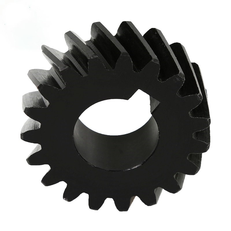
Key to Precision Gear Manufacturing: Installation and Adjustment of Change Gears and Idler Gears | Gearseiko
In high-end precision gear manufacturing, every operational detail dictates the quality of finished products. As a specialist in premium precision gear production, Gearseiko fully recognizes that correct installation and tuning of change gears and idler gears are vital to guaranteed machining accuracy. Below we share our proven expertise in assembling and commissioning these core components, to help gear manufacturers elevate overall product quality.
Why Change Gears and Idler Gears Matter Greatly
In gear machining, the surface condition and meshing clearance of change gears and idler gears exert a direct impact on workpiece precision. Notably, heavy tooth flank damage or oversize meshing gaps on indexing change gears will enlarge common normal length deviation, which further impairs gear transmission smoothness and shortens service life. Years of on-site practice prove that a large number of machining defects stem from improper installation of the change gear system.
Mandatory Pre-Installation Inspections
Before assembling and adjusting change gears and idler gears, our technical team requires three essential inspection items:
1. Tooth Flank Inspection
Examine tooth flanks thoroughly for dents, burrs and abnormal wear. Even slight defects will be magnified at high running speed and undermine machining accuracy. Repair or replace defective gears without delay once issues are found.
2. Check Transmission Accessories
Confirm change gear shafts, bushings, keys, washers and locknuts are complete and free of damage. These small parts, if faulty, will directly trigger transmission malfunction.
3. Bushing Flexibility Test
This easily neglected step is critical. Bushings for change gears and idler gears must rotate flexibly and smoothly. A seized bushing will cause gear disengagement, resulting in sudden tooth misalignment, tool breakage and workpiece scrap, which may lead to serious operational accidents.
Strict Control over Meshing Clearance
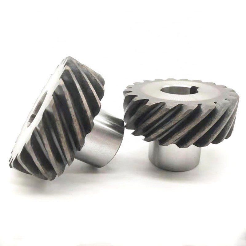
Based on our engineering experience, the meshing clearance of change gears shall be strictly controlled within 0.10 mm to 0.20 mm.
- Insufficient clearance increases running resistance, causes excessive heat build-up and even component seizure.
- Excessive clearance generates impact load and loud noise, and lowers machining accuracy.
Use a feeler gauge or dial indicator for precise measurement to ensure all meshing positions comply with the standard.
No-Load Trial Run and Direction Calibration
Never start formal cutting right after installation. A no-load trial run is mandatory to verify operating status:
- Check whether the hob rotates in the correct direction.
- Confirm the workpiece rotation direction conforms to process rules.
- Ensure the hob head moves smoothly during operation.
- Verify proper matching of driving and driven gears inside the differential gear train.
If rotation direction is wrong, add or remove one idler gear for correction. This is the core function of idler gears: reverse transmission direction while keeping the gear ratio unchanged. Reasonable selection of idler gear quantity and mounting position ensures synchronized movement of the entire transmission chain.
Professional Recommendations from Gearseiko
We suggest establishing a complete standardized maintenance regime for change gears and idler gears:
- Regular inspection: Conduct routine checks at the start of each shift and comprehensive full inspections on a weekly basis.
- Cleaning and lubrication: Keep gear surfaces clean and apply specified lubricating oil periodically.
- Spare parts management: Maintain sufficient stock of commonly used change gears and idler gears to realize rapid replacement of damaged parts.
- Skill training: Make sure all operators master standard installation and adjustment procedures.
Conclusion
Though installation and adjustment of change gears and idler gears look like basic work, they are the cornerstone of stable gear machining accuracy. Gearseiko keeps delivering top-tier precision gears and full technical support to global clients. Feel free to reach out to our engineers if you encounter any technical difficulties in gear processing. We believe that excellence in gear manufacturing comes from perfecting every single detail.
Gearseiko – Precision Transmission, Craftsmanship Driven
FAQ | Change Gears & Idler Gears Installation and Adjustment
Q1: What problems will improper change gear meshing clearance cause?
A1: Too small clearance leads to overheating and seizure; too large clearance causes impact, noise and reduced accuracy.
Q2: What pre-installation checks are required for change gear sets?
A2: Inspect tooth flank condition, integrity of all transmission parts and flexible rotation of bushings.
Q3: What is the standard meshing clearance for change gears?
A3: The meshing clearance shall be controlled between 0.10 mm and 0.20 mm.
Q4: How to correct wrong rotation direction of transmission components?
A4: Add or remove an idler gear to adjust direction without changing the gear ratio.
Q5: What daily maintenance rules are recommended for these gears?
A5: Stick to regular inspection, timely cleaning & lubrication, spare part reserve and operator skill training.
Accuracy and Techniques for Hob Installation
The Critical Role and Application of Idler Gears in Precision Gear Hobbing
Related Article



