
How Gearseiko Sets New Standards in High End Worm Gear Machining
author: Cash
2026-07-13
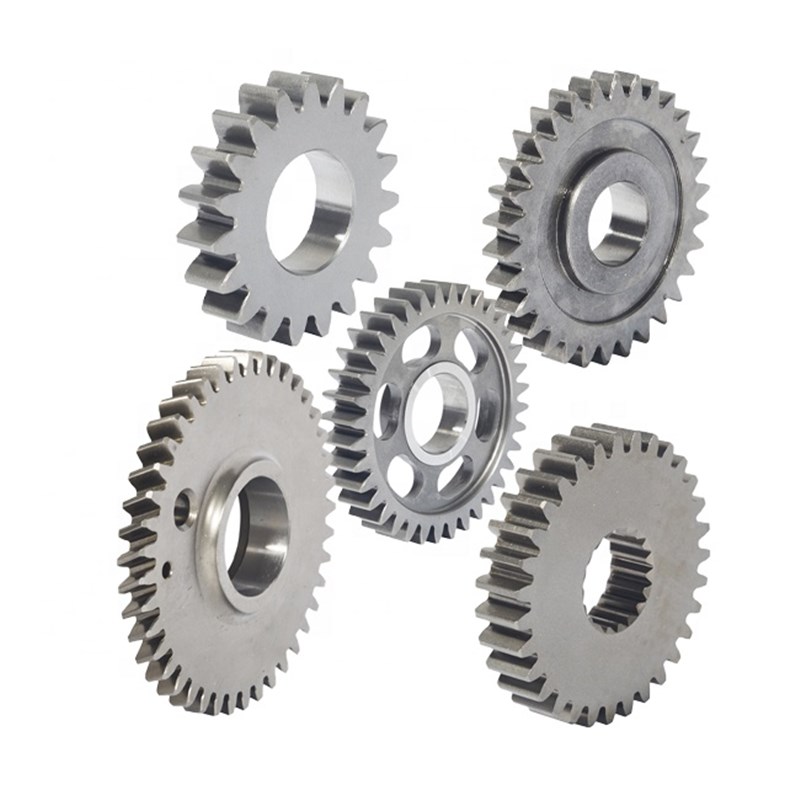
The Precision of Fly Cutter Tooth Profile Design: How Gearseiko Sets New Standards in High-End Worm Gear Machining | Gearseiko
Introduction
In the realm of precision power transmission systems, the meshing performance of worm and worm gear pairs serves as the core determinant of overall system accuracy, operational reliability, and long-term service life. Among mainstream worm gear machining technologies, the fly cutter generating process stands out for its outstanding flexibility and cost-effectiveness, making it the ideal solution for single-piece customization, small-batch production, and large-module worm gear manufacturing.
The core essence of fly cutter machining lies in tooth profile design: a fly cutter tip functionally equates to a single independent tooth of a standard worm gear hob, and its profile accuracy directly governs the dimensional precision, surface quality, and meshing coordination of finished worm gears. As a professional manufacturer specializing in high-end precision gear production, Gearseiko has accumulated in-depth technical insights and mature engineering experience in customized fly cutter profile design. We fully recognize that different worm drive types impose completely differentiated profile requirements for fly cutters. Adhering to rigorous mechanical transmission principles, we deliver targeted, high-precision fly cutter design solutions to help global customers achieve stable, high-quality worm gear machining results.
1. Core Design Principles of Fly Cutter Generative Machining
The fundamental design logic of fly cutters is highly consistent with that of traditional precision worm hobs. The mandatory design criterion is that all side cutting edges of the fly cutter must fit perfectly on the helical surface of the basic worm, so as to simulate standard conjugate meshing motion and realize accurate generative forming of worm gear teeth.
Given the diverse helical surface geometries of different industrial worm drives, a universal fly cutter profile cannot meet differentiated machining demands. Blindly adopting unified profile design will lead to meshing deviation, tooth flank distortion and reduced transmission efficiency. Gearseiko’s technical team strictly follows the structural characteristics of ZN and ZA worm drives to develop matched fly cutter profiles and installation schemes, ensuring zero theoretical error in tooth forming and perfect meshing coordination between finished worm gears and mating worms.
2. Normal Straight-Sided (ZN) Worm Drives: High-Precision Straight Edge Profile Realization
For worm gear pairs supporting normal straight-sided (ZN) worm drives, the fly cutter profile features a standardized linear structure that fully corresponds to the normal section contour of the matched working worm. Its cutting edges are precise straight lines, and the tool pressure angle is strictly consistent with the worm’s normal pressure angle.
In terms of tool installation, the fly cutter’s rake face must be accurately positioned on the worm’s normal section plane after being fixed on the cutter arbor. Though this design principle is intuitive and concise, it imposes ultra-high requirements on tool positioning accuracy and grinding precision, with tiny deviations enough to affect the overall meshing performance of ZN worm gear pairs.
Equipped with high-precision CNC tool grinding equipment and implementing full-process strict inspection standards, Gearseiko optimizes every production link of ZN worm fly cutters. We fully guarantee the straight-edge flatness, pressure angle accuracy and installation angle consistency of finished tools, providing solid and reliable technical support for efficient, high-precision batch machining of standard ZN worm gears.
3. Archimedean (ZA) Worm Drives: Lead Angle-Based Differentiated Profile Strategy
As the most widely applied worm type in industrial transmission equipment, Archimedean (ZA) worms feature an Archimedean spiral transverse profile and a linear axial profile. Their unique structural characteristics determine that fly cutter profile design cannot adopt a unified scheme. Gearseiko classifies and optimizes fly cutter solutions based on the critical parameter of worm lead angle, realizing targeted precision machining for different working conditions.
3.1 Small Lead Angle (γ ≤ 5°): Simplified Axial Straight-Edge Design
When the ZA worm lead angle is ≤ 5°, the helical surface distortion is negligible. In this scenario, the fly cutter rake face can be installed on the axial section of the cutter arbor, functioning exactly as a single-tooth straight-flute worm hob. Both side cutting edges maintain standard linear shapes, and the tool pressure angle matches the axial pressure angle of the Archimedean worm.
This design boasts simple manufacturing procedures, easy grinding accuracy control and stable forming effect. It is the most cost-effective and reliable solution for machining small-lead-angle and single-start ZA worm gears, covering most conventional small and medium-module industrial processing scenarios.
3.2 Large Lead Angle (γ > 5°): Optimized Curved Profile Customization
When the worm lead angle exceeds 5°, the traditional axial installation scheme will cause severe asymmetry in the rake angles of the fly cutter’s two side edges — one side presents a positive rake angle while the other is negative. The unbalanced cutting state leads to inconsistent cutting resistance on both sides, easily producing periodic waviness and micro-distortion on the worm gear tooth flanks, which seriously affects transmission stability and surface finish.
To solve this industry pain point, Gearseiko formulates two differentiated optimization schemes for large-lead-angle ZA worm machining:
Special grinding process for large-module workpieces: We adopt professional customized grinding technology to balance the rake angles of the left and right cutting edges completely, ensuring consistent cutting performance on both sides and maintaining ultra-high profile accuracy. This complex and precise process is specially applied to high-value, large-module worm gear production scenarios with strict precision requirements.
Normal mounting scheme for small and medium-module workpieces: For conventional small and medium-module ZA worm gears, we abandon axial installation and adopt normal-direction positioning. This setup enables zero rake angle symmetry for both cutting edges, completely eliminating unbalanced cutting stress. Meanwhile, the fly cutter profile changes from linear to curved, which needs to perfectly fit the normal section curved profile of the Archimedean worm.
Leveraging independent mathematical modeling, accurate coordinate calculation, advanced CNC machining and precision grinding technology, Gearseiko completes full-point fitting and ultra-precision manufacturing of curved profiles. Every custom fly cutter strictly conforms to theoretical design standards, thoroughly solving the profiling error problem of large-lead-angle ZA worm gears.
4. Gearseiko’s Core Technical Advantages in Fly Cutter Profile Design
Gearseiko’s leading competitiveness in high-end fly cutter customization and worm gear machining is built on three solid technical pillars, achieving comprehensive advantages in theoretical accuracy, scheme flexibility and manufacturing quality.
Accurate theoretical grasp: Our engineering team thoroughly masters the intrinsic geometric differences of ZN and ZA worm helical surfaces, accurately identifies the profile and installation requirements of fly cutters under different lead angles and module specifications, and eliminates fundamental theoretical errors from the design source.
Flexible customized solutions: We do not adopt rigid standardized processing modes. According to customers’ actual parameters including worm lead angle, module, start number and application scenarios, we flexibly match the optimal fly cutter profile structure and installation scheme, adapting to diversified personalized production demands.
Rigorous manufacturing quality control: Supported by high-precision CNC grinding equipment and complete testing instruments, we implement full-process quality inspection from profile modeling, rough machining to finish grinding. Every finished fly cutter features excellent profile consistency, high dimensional accuracy and stable cutting performance.
Conclusion
High-precision fly cutter tooth profile design is the core foundation of high-end worm gear generative machining. ZN straight-sided worms and ZA Archimedean worms require completely differentiated profile design logic; ZA worms further need classified optimization based on lead angle to avoid cutting imbalance and tooth surface defects.
Breaking the limitations of traditional crude unified-profile processing, Gearseiko relies on professional transmission theory, flexible customized solutions and ultra-precision manufacturing craftsmanship to set new industry standards for fly cutter design and worm gear machining. Whether for standard straight-edge fly cutters for ZN worms or high-precision curved-profile fly cutters for large-lead-angle ZA worms, we consistently deliver stable, reliable, high-cost-performance tooling and gear products for global industrial power transmission equipment.
FAQ | Fly Cutter Tooth Profile Design & High-End Worm Gear Machining
Q1: Why can’t fly cutters adopt a unified profile for all worm types?
A1: Different worm types have distinct helical surface geometries. ZN worms require linear normal-section profiles, while ZA worms need differentiated linear or curved profiles based on lead angles. A unified profile will cause theoretical meshing errors, tooth flank waviness and unqualified transmission performance.
Q2: What are the characteristics of fly cutter design for ZN normal straight-sided worms?
A2: ZN worm fly cutters adopt standard straight cutting edges with a pressure angle consistent with the worm’s normal pressure angle. The rake face must be precisely positioned on the worm’s normal section, requiring ultra-high tool positioning and grinding accuracy to ensure perfect meshing.
Q3: What problems will large lead angle ZA worms encounter with traditional axial-installed fly cutters?
A3: Traditional axial installation causes asymmetric positive and negative rake angles on two cutting edges, leading to unbalanced cutting conditions, uneven tool wear, and wavy defects on worm gear tooth flanks, which reduce precision and service life.
Q4: What solutions does Gearseiko adopt for large lead angle ZA worm fly cutters?
A4: For large-module workpieces, we use special grinding to balance bilateral rake angles; for small and medium-module workpieces, we adopt normal-direction installation with customized curved profiles matching the ZA worm’s normal section to eliminate cutting imbalance.
Q5: What advantages does Gearseiko’s customized fly cutter design have?
A5: We combine accurate theoretical calculation, scenario-based differentiated schemes and full-process precision manufacturing. Our custom fly cutters eliminate theoretical errors, optimize cutting conditions, and significantly improve worm gear meshing accuracy, surface quality and operational stability.
Q6: What application scenarios are Gearseiko’s custom fly cutters suitable for?
A6: They are widely applicable for single-piece prototype customization, small-batch production and large-module machining of ZN and ZA worm gears, covering industrial machinery, automation equipment and high-end precision transmission systems.
Solutions and Precision Gear Solutions from Gearseiko
How Gearseiko Empowers High End Worm Wheel Machining with Craftsmanship
Related Article



