
Calculation of bending stress at tooth root
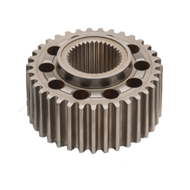
Root Bending Stress Calculation: The Core Technology for Ensuring Reliability of Aerospace Planetary Gear Drives
In high-performance transmission systems, root bending fatigue fracture is one of the most common and dangerous failure modes of gears. For aerospace gears, which typically have small modules to save weight and space, the root bending fatigue strength is inherently limited. This poses a critical challenge in planetary gear drives, where a single broken tooth can jam the entire mechanism. The consequences are severe: an engine may burn out due to overload, or the complete drivetrain may be destroyed in an instant. Therefore, accurate assessment of root bending fatigue strength is not just a design preference — it is the key reliability indicator for aerospace planetary gear systems.
At Gearseiko, a factory dedicated to manufacturing high-end precision gears, we have built our engineering philosophy around this fundamental truth. We take root bending fatigue strength as the primary reliability assessment parameter for all our planetary gear products. Through advanced simulation technology, rigorous material control, and decades of practical experience, we ensure that every gear maintains exceptional bending fatigue resistance even under extreme operating conditions — including high rotational speeds, heavy loads, temperature fluctuations, and lubrication starvation.
Maximum Root Bending Stress and the Critical Loading Position
The root bending stress in a gear tooth is essentially the maximum tensile stress generated on the loaded side of the tooth root surface during meshing. This tensile stress is the driving force behind crack initiation and propagation. The classical expression for calculating this peak stress is:
Where:
-
σFσF = maximum root bending stress
-
KK = load factor (including dynamic effects, load distribution, and overload)
-
TT = applied torque
-
bb = face width
-
dd = pitch diameter
-
mm = module
-
YY = combined tooth shape and stress correction factor
The calculated peak tensile stress corresponds to the most severe loading condition in each meshing cycle. The position along the tooth flank where this peak occurs is defined as the critical loading position — the exact location where fatigue cracks are most likely to initiate and eventually propagate into complete tooth fracture.
At Gearseiko, we do not stop at simply calculating this peak value. We recognize that a gear tooth experiences a varying stress history during each engagement. By representing the maximum stress as a series of discrete points over the meshing cycle, we can efficiently describe the entire load history. This discrete representation captures the primary load factors affecting gear reliability — such as torque fluctuations, meshing phase differences, and manufacturing deviations — while significantly reducing the computational burden of our simulation models. This approach allows us to perform comprehensive, full-system simulations without excessive computation time.
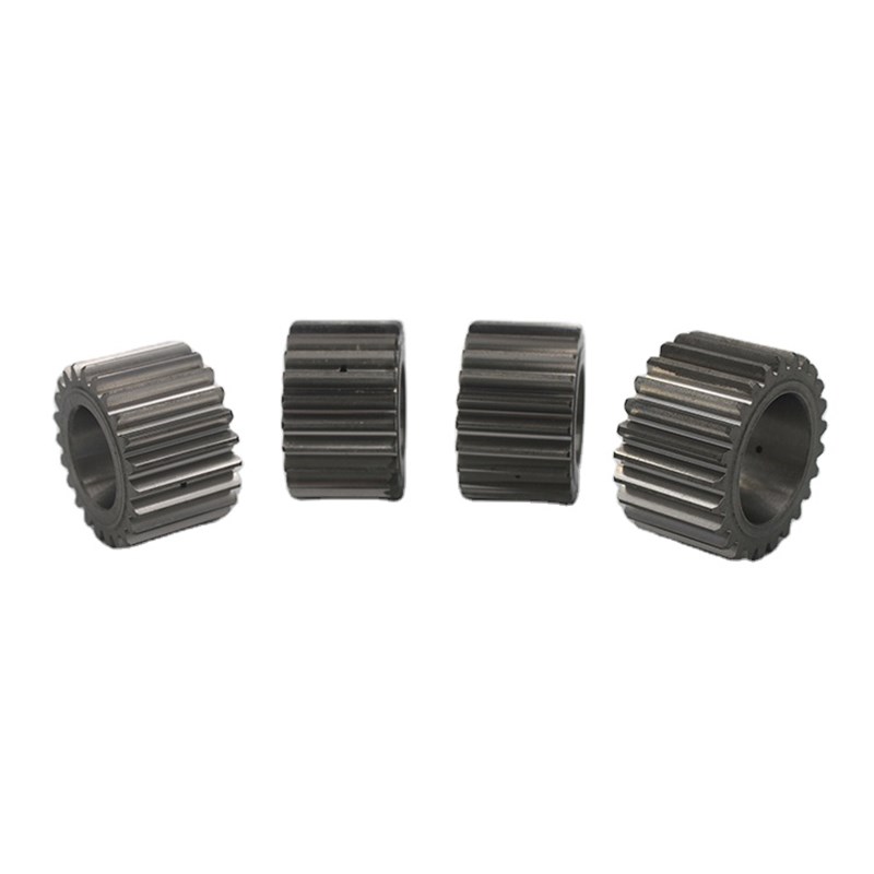
Multi-Factor Coupling: Moving Beyond Basic Formulas
In real-world operation, especially in aerospace environments, gears are subjected to far more complex loading conditions than those described by the basic formula. Several additional physical phenomena significantly affect root bending stress:
-
Friction – Tangential forces from relative sliding between mating tooth flanks alter the root stress distribution, creating additional tensile or compressive components depending on the sliding direction.
-
Centrifugal force – At high rotational speeds (common in aero-engines and helicopter transmissions), the tooth mass itself generates a centrifugal tensile stress that adds directly to the bending stress, raising the peak value.
-
Thermal effects – Temperature gradients across the gear body cause differential thermal expansion, affecting both material properties and meshing geometry. High-temperature operation can reduce yield strength and accelerate fatigue.
-
Elastic deformation of support components – Shafts, bearings, planet carriers, and housings are not perfectly rigid. Their deflections and deformations change the actual meshing positions, misalign teeth, and redistribute loads among multiple planet gears. This can significantly increase root stress on certain teeth.
Ignoring any of these factors can lead to dangerous under-design. Gearseiko therefore uses industry-leading gear transmission analysis and calculation tools (specialized software widely adopted in aerospace and automotive engineering) to build high-precision simulation models of planetary gear drives. These models incorporate all the above factors through a series of correction coefficients, ensuring that simulation results closely match real-world strain gauge measurements.
From Stress Calculation to Practical Reliability Assessment
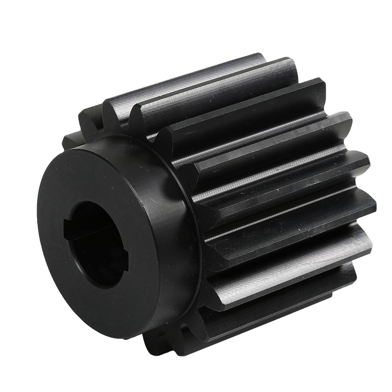
The process of calculating root bending stress at Gearseiko follows a structured, data-driven workflow:
-
Step 1: Load spectrum analysis – We collect or derive the torque-speed-time history for the specific aerospace application (e.g., takeoff, cruise, landing, emergency conditions).
-
Step 2: Gear macro-geometry definition – Module, number of teeth, pressure angle, helix angle, face width, and profile shift are defined to satisfy both strength and noise requirements.
-
Step 3: Critical load position identification – Using finite element analysis (FEA) or analytical methods, we locate the worst-case meshing position for each tooth.
-
Step 4: Multi-factor coefficient determination – Correction factors for friction, centrifugal force, thermal effects, and support deformations are calculated iteratively.
-
Step 5: Root bending stress calculation – The enhanced formula yields peak tensile stress values, which are compared against the material’s allowable fatigue strength.
-
Step 6: Reliability assessment – Based on the calculated stress and scatter in material properties, we determine the predicted probability of root bending fatigue failure over the required service life.
Gearseiko’s engineering team has extensive experience in calibrating these coefficients for different gear types (external, internal, planet gears) and various operating conditions. We maintain an internal database of validated simulation results against physical testing, which continuously improves our accuracy.
Why Gearseiko Stands Out in Root Bending Stress Management
For a precision gear factory, accurate root bending stress calculation is only the first step. The real value lies in translating those calculations into manufacturing processes that deliver the predicted strength. At Gearseiko, we do this through:
-
Optimized root fillet geometry – Using CNC gear grinding and specialized cutters, we achieve a smooth, large-radius root fillet that minimizes stress concentration.
-
Controlled surface finish – Shot peening and superfinishing reduce surface roughness and introduce beneficial compressive residual stresses at the root, significantly delaying crack initiation.
-
Material and heat treatment precision – We use high-quality alloy steels (e.g., case-hardened grades) with strict control over case depth, core hardness, and retained austenite content.
-
Non-destructive testing (NDT) – Every critical gear is inspected for root surface cracks or inclusions using magnetic particle or eddy current methods.
-
Validation testing – We perform accelerated fatigue tests on prototype gears to confirm that the calculated root bending strength matches actual performance.
Conclusion
In aerospace planetary gear drives, reliability is not an option — it is a lifeline. A single tooth failure can lead to catastrophic engine or drivetrain loss. Root bending fatigue strength is the most meaningful reliability indicator, and accurate root bending stress calculation is the foundation of safe gear design.
Gearseiko combines advanced simulation, multi-factor correction, and precision manufacturing to deliver gears that consistently meet or exceed root bending fatigue requirements. Whether you need gears for jet engines, helicopter main rotors, or high-performance industrial planetary reducers, our products are engineered to withstand the toughest bending stress environments.
Choose Gearseiko – where every tooth root is designed for endurance.
Equivalent transformation of load
Analysis and Calculation of the Partial Load Behavior of Helicopter Planetary Gear Transmission System
Related Article



