
Analysis and Calculation of the Partial Load Behavior of Helicopter Planetary Gear Transmission System
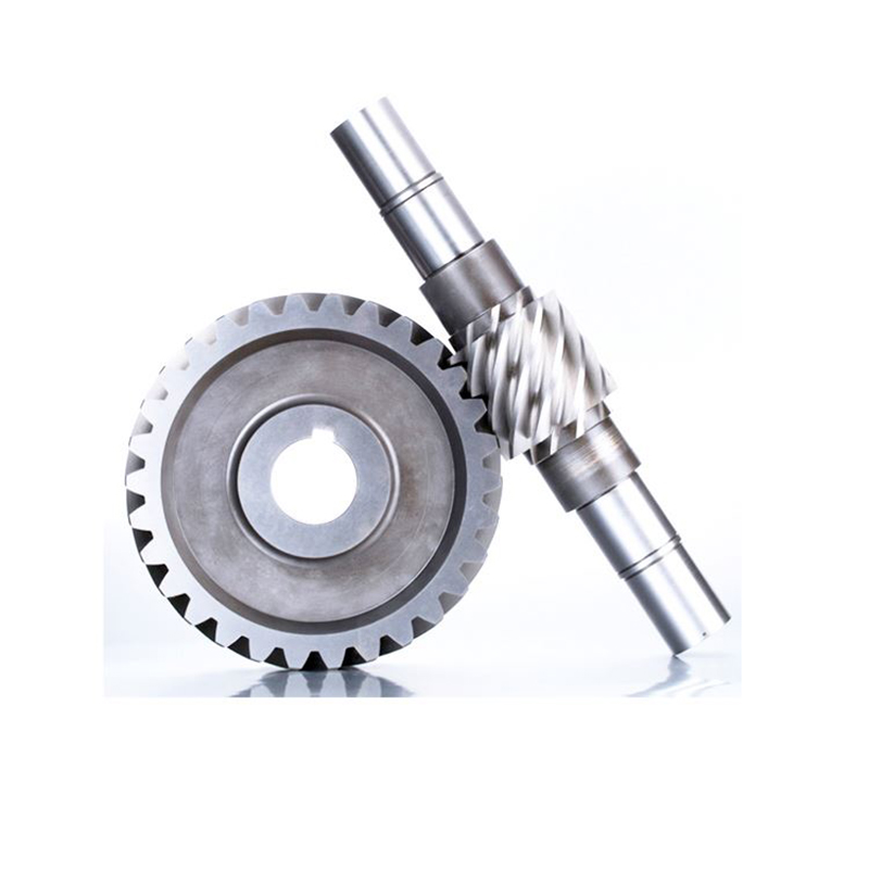
Helicopter Planetary Gear Misalignment: Analysis, Calculation, and Precision Solutions from Gearseiko
Planetary gear systems are widely recognized as the backbone of modern helicopter drivetrains. Their inherent advantages – compact size, low weight, smooth operation, high power density, and excellent durability – align perfectly with the stringent demands of aero-engine applications. However, one challenge that persistently threatens the reliability and safety of these systems is misalignment behavior. When misalignment reaches a critical level, the load environment deteriorates rapidly, compromising transmission stability and service life. For aviation, where any drivetrain failure can lead to catastrophic consequences, understanding and mitigating misalignment is not optional – it is essential.
At Gearseiko, we specialize in high-end precision gears for mission-critical applications. Our approach combines deep physical insight into misalignment mechanisms, advanced calculation methods, and proven design strategies to deliver planetary gear systems that perform reliably even under extreme conditions.
Why Misalignment Matters in Helicopter Transmissions
Helicopter main gearboxes typically employ planetary stages to achieve high reduction ratios in a confined space. The power-splitting architecture – where multiple planet gears share the load between a sun gear and a ring gear – offers remarkable torque-to-weight ratios. Yet this very architecture is sensitive to manufacturing tolerances, assembly variations, elastic deflections, and thermal gradients. Even minor deviations can cause uneven load distribution among planet gears or non-uniform contact stress along the tooth width.
The consequences are severe:
-
Accelerated fatigue: Overloaded teeth experience contact stresses well above the design limit, leading to micropitting, spalling, or root cracking.
-
Reduced lubricant effectiveness: Localized high pressure breaks the oil film, causing mixed or boundary lubrication and increasing wear.
-
Vibration and noise: Misalignment introduces periodic excitation, amplifying dynamic loads and reducing ride comfort.
-
Catastrophic failure: In extreme cases, a single tooth fracture can cascade into complete transmission seizure, endangering the aircraft and crew.
Therefore, any credible manufacturer of helicopter planetary gears must not only be able to analyze misalignment behavior but also implement effective countermeasures from the design stage through manufacturing and assembly.
Types of Misalignment in Planetary Systems
From an engineering standpoint, we distinguish two primary forms of misalignment:
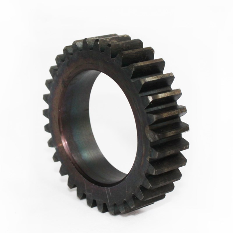
1. Axial Misalignment (Tooth Lead Misalignment)
Axial misalignment occurs when the line of contact between mating teeth is not parallel to the gear axis. In helical planetary gears, this results in a triangular or trapezoidal load distribution across the face width – one edge of the tooth carries significantly more load than the other. Common causes include:
-
Shaft bending under load
-
Housing or carrier misalignment
-
Lead errors from grinding or hobbing
-
Thermal distortion during operation
2. Radial Misalignment (Load Sharing Imbalance)
Radial misalignment refers to uneven torque distribution among the multiple planet gears. Ideally, each planet wheel should carry an equal share of the total load. In reality, due to eccentricities, bearing clearances, and carrier elasticity, some planets may be overloaded while others are underloaded. The load sharing factor (LSF) – defined as the maximum planet load divided by the average planet load – typically ranges from 1.1 to 1.5 in unoptimized systems. An LSF exceeding 1.3 is considered critical for high-reliability aviation applications.
These two misalignment types often interact. For example, axial misalignment changes the effective mesh stiffness of each planet, which in turn influences radial load sharing.
Quantitative Calculation of Misalignment Behavior
Accurate prediction of misalignment is the foundation of robust design. Gearseiko employs a multi-step computational methodology:
Step 1 – Component-Level Error Mapping
We begin by measuring or specifying all relevant deviations: tooth lead error, profile error, pitch error, bearing clearance, carrier bore position tolerances, and housing parallelism. These are compiled into an error vector that serves as input for system-level simulation.
Step 2 – Finite Element Contact Analysis (FECA)
Using three-dimensional finite element models of the gear pair, we calculate the contact stress distribution along the tooth flank under nominal and worst-case misalignment conditions. The analysis outputs:
-
Peak contact stress (σ_H,max)
-
Load distribution factor (K_Hβ for axial misalignment)
-
Edge contact severity index
Step 3 – System-Level Load Sharing Simulation
A multi-body dynamics model of the complete planetary stage – including sun gear, carrier, ring gear, all planet gears, bearings, and shafts – is built. We apply the actual torque profile and rotational speed, then solve for the instantaneous load on each planet gear. The results are expressed as the load sharing factor (LSF) and the dynamic misalignment coefficient.
Step 4 – Life Prediction Under Misaligned Conditions
Finally, we integrate the calculated stress distributions with material fatigue data (e.g., AGMA or ISO gear life models) to estimate the reduction in service life caused by misalignment. This allows us to quantify the benefit of design improvements.
Case Example: For a 1,500 kW helicopter main gearbox planetary stage, Gearseiko’s baseline analysis showed an axial misalignment coefficient K_Hβ = 1.28 and an LSF of 1.33, which would reduce predicted bearing life by 40% and gear contact fatigue life by 55%. After applying our optimized lead crowning and carrier stiffness tuning, K_Hβ dropped to 1.06 and LSF to 1.09, restoring 90% of the theoretical gear life.
Gearseiko’s Integrated Anti-Misalignment Strategy
At Gearseiko, we do not rely on a single “magic fix.” Instead, we implement a holistic strategy spanning design, manufacturing, and assembly:
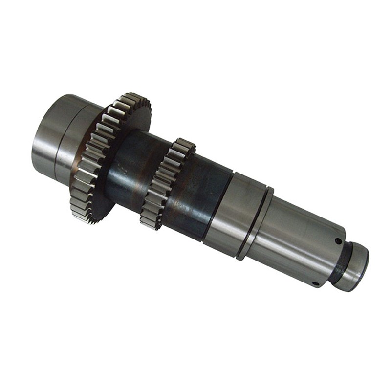
1. Precision Tooth Modifications
-
Lead crowning: A smooth convex profile along the face width compensates for expected shaft deflection and misalignment, preventing edge contact.
-
Tip relief and root optimization: Reduces mesh impact and stress concentration.
-
Topological modifications: Customized 3D flank form derived from our FECA results.
2. Flexible and Floating Elements
-
Floating sun gear: Allows radial self-alignment to equalize planet loads.
-
Flexible pin or flexspline carrier design: Introduces controlled compliance that passively distributes load more evenly.
3. Ultra-Precision Manufacturing
-
Gear quality to ISO 4 or AGMA 15 equivalent.
-
Dedicated grinding and superfinishing processes for surface roughness Ra ≤ 0.1 μm.
-
100% inspection using CNC gear measuring centers and coordinate measuring machines.
4. Assembly Compensation
-
Selective assembly of planet gears based on measured bore positions and tooth lead deviations.
-
Use of adjustable bearing preload or shims to minimize residual misalignment.
5. Validation Testing
-
Strain gauge instrumentation on planet gear roots under loaded test rig conditions.
-
Thermal imaging of tooth flank temperature to detect misalignment-induced hot spots.
Conclusion: Precision You Can Rely On
Misalignment in planetary gear systems is unavoidable – but its harmful effects can be contained through rigorous analysis, intelligent design, and meticulous manufacturing. For helicopter applications, where safety margins are non-negotiable, partnering with a specialist like Gearseiko ensures that every gear is optimized to maintain uniform load distribution across all operating conditions.
We don’t just produce gears; we engineer trust. Whether you are developing a next-generation tiltrotor or upgrading an existing fleet, Gearseiko’s expertise in misalignment analysis and calculation will help you achieve longer life, lower vibration, and higher mission readiness.
Contact Gearseiko today to discuss your planetary gear requirements. Let us show you how precision engineering transforms potential failure into reliable performance.
Calculation of bending stress at tooth root
Load Analysis and Calculation of Planetary Gear Transmission System
Related Article



