
A Key Technology for Improving Precision Transmission
author: Cash
2026-06-06
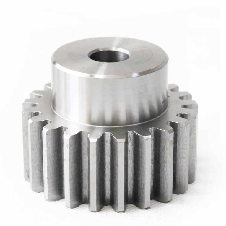
Geometric Calculation of Dual-Lead Worm Drives: A Key Technology for Improving Precision Transmission | Gearseiko
Precision consistency and long-running dimensional stability stand as core performance benchmarks for high-end modern machinery manufacturing. Featuring adjustable backlash compensation via axial displacement, dual-lead worm gear pairs are widely adopted in high-precision industrial equipment including CNC machine tools, boring-milling composite spindle heads and precision indexing rotary tables. This article systematically elaborates core geometric calculation rules of dual-lead worm drives to support engineering designers in standardized parameter layout and maximize adjustable backlash design benefits in practical equipment matching.Reach Gearseiko’s technical team to obtain free dual-lead worm geometric calculation service and customized quotation for precision worm drive project.
Definition & Operating Principle of Dual-Lead Worm Drive
The basic meshing mechanism aligns with standard cylindrical worm gearing: axial-section tooth contour of straight axial-profile worm simulates rack profile, while matched worm wheel works as conjugate involute gear for continuous rolling meshing. The core differentiating feature of dual-lead worm lies in inconsistent lead values on left and right tooth flanks, yet single flank keeps fixed constant lead.
Divergent lead between bilateral tooth surfaces triggers linearly progressive axial tooth thickness variation along worm length (gradual thickening or thinning). When implementing axial sliding adjustment on finished worm component, the overall meshing backlash of worm set changes synchronously. This structural merit realizes active wear compensation: after long-cycle operation, tooth surface abrasion enlarges meshing clearance and impairs positioning precision; designers simply shift worm toward thinning-tooth side axially to eliminate excessive backlash and restore original design transmission accuracy. For this unique property, dual-lead worm is also named variable tooth thickness worm in industrial specifications.
Core Geometric Calculation Specifications for Dual-Lead Worm Drive Design

Three key parameter groups require rigorous computing during structural design:
1. Nominal Module & Circumferential Tooth Pitch
Unlike standardized ordinary worm specifications, dual-lead worm rarely applies fixed standard module; nominal module is defined by tooth pitch measured on worm wheel nominal pitch circle diameter. Design engineers configure nominal module matching practical load magnitude, total reduction ratio and installation space limitation to guarantee rated load capacity and high mechanical transmission efficiency.
2. Bilateral Flank Lead & Corresponding Helix Angle
Left and right tooth flanks share identical axial or normal pressure angle in most mature design schemes, but differ distinctly in lead and equivalent module, further generating non-uniform nominal cylinder helix angle on two sides. The lead discrepancy serves as the fundamental precondition of linear tooth thickness change and adjustable backlash function. Design must separately compute lead and helix angle for each flank, then complete conjugate meshing verification between worm and worm wheel against nominal pitch diameter and tooth pitch data to satisfy assembly and precision constraints.
3. Machining Geometric Tolerance Control
For CNC turning and grinding forming of dual-lead worm helicoid: interchange gear configuration is separately computed and selected corresponding to respective lead of left/right flank; abrasive wheel mounting inclination angle during finish grinding needs independent calibration based on each flank’s nominal pitch cylinder helix angle. Such segmented processing raises equipment flexibility requirement and puts forward higher computational threshold for technical process engineers.
Gearseiko Mature Precision Production Advantage for Dual-Lead Worm Sets
Focused on high-end precision gear and worm drive R&D and batch manufacturing, Gearseiko has accumulated abundant practical experience covering dual-lead worm geometric optimization and high-precision finish machining. Equipped with professional CNC worm grinding machines and three-coordinate precision inspection system, our production strictly controls bilateral flank lead deviation, axial linear tooth thickness tolerance and preset initial meshing backlash. All finished worm and wheel pairs retain reliable adjustment performance and superior meshing precision after delivery.
Our customized dual-lead worm solutions serve multiple high-precision sectors: machine tool indexing spindle structure, radar angle tracking equipment and ultra-precision rotary indexing table. Users compensate operation abrasion only via simple axial worm shifting to prolong whole transmission assembly service lifespan and cut later maintenance expense.

Summary & Custom Cooperation
Benefiting from inherent variable tooth thickness and adjustable backlash advantages, dual-lead worm gearing becomes irreplaceable core part for high-accuracy positioning transmission. Mastering standardized geometric calculation improves drive durability and operational efficiency while lowering end-user maintenance cost and boosting equipment availability rate.
Gearseiko keeps optimizing dual-lead worm design and processing technology to supply stable high-performance drive products for global clients. Submit your load, speed and precision requirement to our engineers for exclusive design, parameter calculation and OEM production service.
FAQ | Dual-Lead Worm Drive Geometry & Fabrication
Q1: What is the core structural characteristic of dual-lead worm?
A1: Different lead on left and right tooth flank, constant lead on single flank leading to linearly changed axial tooth thickness for backlash adjustment.
Q2: How does dual-lead worm realize wear compensation?
A2: Axially move worm toward tooth-thinning direction to reduce enlarged meshing backlash caused by long-term abrasion.
Q3: How to confirm nominal module of dual-lead worm set?
A3: Nominal module is determined by tooth pitch on worm wheel nominal pitch diameter without fixed standard size.
Q4: Key machining difference vs ordinary standard worm?
A4: Separate change gear calculation and grinding wheel angle setting for left and right flank due to inconsistent lead and helix angle.
Q5: Main typical application fields of dual-lead worm drives?
A5: CNC machine tool indexing head, boring-milling head, precision rotary table and radar tracking transmission.
How Gearseiko Redefines High-Precision Gear Manufacturing
High‑Precision Solutions from Gearseiko
Related Article



